Table of Contents
Advertisement
Quick Links
Owner's Manual
8-Port Unmanaged Industrial
Gigabit 10/100/1000 Ethernet
Switch with EIP QoS, DIN or
Wall-Mountable
Este manual está disponible en español en la página de Tripp Lite:
Ce manuel est disponible en français sur le site Web de Tripp Lite :
Русскоязычная версия настоящего руководства представлена на
веб-сайте компании Tripp Lite по адресу: tripplite.com
Dieses Handbuch ist in deutscher Sprache auf der Tripp Lite-Website
WARRANTY REGISTRATION
automatically entered to win an ISOBAR
surge protector in our monthly drawing!
1111 W. 35th Street, Chicago, IL 60609 USA • tripplite.com/support
Copyright © 2022 Tripp Lite. All rights reserved.
Model: NGI-U08A
tripplite.com
tripplite.com
verfügbar: tripplite.com
Register your product today and be
tripplite.com/warranty
1
®
Advertisement
Table of Contents

Related Manuals for Tripp Lite NGI-U08A


Summary of Contents for Tripp Lite NGI-U08A
- Page 1 Model: NGI-U08A Este manual está disponible en español en la página de Tripp Lite: tripplite.com Ce manuel est disponible en français sur le site Web de Tripp Lite : tripplite.com Русскоязычная версия настоящего руководства представлена на веб-сайте компании Tripp Lite по адресу: tripplite.com Dieses Handbuch ist in deutscher Sprache auf der Tripp Lite-Website verfügbar: tripplite.com...
-
Page 2: Package Contents
Package Contents • NGI-U08A 10/100/1000 Ethernet Switch with EIP QoS • DIN Rail-Mounting Clip (Preinstalled) • Owner’s Manual Product Features • 8 auto-negotiable 10/100/1000 Mbps RJ45 ports • Supports 10/100/1000Base-T, Full Duplex and auto MDI/MDI-X crossover function • Simple plug-and-play installation and operation with no configuration required •... -
Page 3: Optional Accessories
Product Features • Supports MAC address auto-learning and auto-aging • EIP/QoS/Flow and Storm Control • Preinstalled durable rail clip mounts firmly to any standard 35 mm DIN rail Optional Accessories • N001-Series Cat5e 350 MHz Snagless UTP Cables • N002-Series Cat5e 350 MHz UTP Ethernet Cables •... -
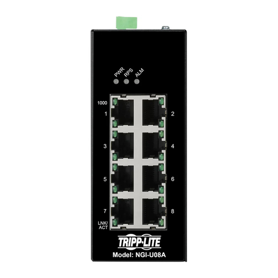
Page 4: Product Overview
Product Overview 8-Port Unmanaged Industrial Gigabit 10/100/1000 Ethernet Switch with EIP QoS, DIN or Wall-Mountable DIN Rail Grounding Screw Power Input Terminal Block 1000 Mbps DIP Switches Top View LNK/ACT Grounding Screw Front View... -
Page 5: Mounting The Switch
DIN-Rail Mounting and Dismounting Instructions ATTENTION: The NGI-U08A is an open-type device and shall be DIN-rail mounted or wall mounted (optional) in a cabinet or rack enclosure. The ambient temperature should not exceed 75°C (167°F). Mounting the Switch Place the switch on the DIN rail from above using the built-in slot. -
Page 6: Grounding The Switch
DIN-Rail Mounting and Dismounting Instructions ATTENTION: A corrosion-free DIN mounting rail is advisable. When mounting the switch, be sure to allow enough space between devices to install the cabling and to ensure proper airflow. Grounding the Switch Grounding and wire routing help limit the effects of line noise caused by electromagnetic interference (EMI). -
Page 7: Wiring Requirements
Wiring Requirements WARNING: Safety measures should be taken before connecting the power cable. Turn off the power before connecting modules or wires. The correct power supply voltage is listed on the product label. Check the voltage of your power source to make sure you are using the correct voltage. -
Page 8: Wiring Power Input
Wiring Requirements Wiring Power Input You can use “PWR” for Primary Power input and “RPS” for Redundant Power Input. Check the polarity while connecting. The top view of the Terminal Block is shown in the figure below: Terminal Block CAUTION: •... - Page 9 Wiring Requirements To insert power wire and connect the specified voltage and maximum electric current to the power terminal block, follow these steps: • Use a flat-head screwdriver to loosen the wire-clamp screws. • Insert the negative/positive DC wires into the PWR-/PWR+ terminals, respectively.
- Page 10 Wiring Requirements Wiring the Relay Contact (ALM) The switch has one set of relay alarm output. This relay contact uses two contacts of the terminal block on the switch top panel. The two contacts of the 6-pin terminal block connector are used to detect user-configured events.
-
Page 11: Dip Switch Settings
Cabling Connect one end of an RJ45 Ethernet cable (see Optional Accessories) into the switch’s RJ45 Ethernet port. Connect the other end to a network device. Cat5e cable or above is recommended. • Ports 1-8 of the switch support Gigabit Ethernet (10/100/1000 Mbp speeds) •... - Page 12 Cabling Port 2 link alarm reporting is enabled Port 2 link alarm reporting is disabled Port 3 link alarm reporting is enabled Port 3 link alarm reporting is disabled Port 4 link alarm reporting is enabled Port 4 link alarm reporting is disabled Port 5 link alarm reporting is enabled Port 5 link alarm reporting is disabled Port 6 link alarm reporting is enabled...
-
Page 13: Led Indicators
LED Indicators Illuminated Primary power on PWR (Green) Primary power off or failure Illuminated Redundant power on RPS (Green) Redundant power off or failure Alarm triggered for abnormal Illuminated power or port link down status ALM (Red) Normal operation or DIP switch off Illuminated Link speed at 1000 Mbps 1000 (Green) -
Page 14: Specifications
Specifications Power Input Voltage Dual-power inputs 12-48VDC/0.5A Connection 6-pin terminal block Reverse Polarity Present Protection Power Consumption (System Only) Grounding Screw Present Interface RJ45 8 x 10/100/1000Base-T, auto-negotiation, auto-MDI/MDI-X, Full/Half Duplex and Flow Control PWR (Green): Power RPS (Green): Power by terminal block RPS ALM (Red): Power and RPS fails and RJ45 port link down 1000 (Green): Port 1~8 1000 Mbps... - Page 15 Specifications Environmental Operating Temperature -40°C to 75°C (-40°F to 167°F) Storage Temperature -40°C to 85°C (-40°F to 185°F) Operating Humidity 5 to 95% (Non-Condensing) Storage Humidity 5 to 95% (Non-Condensing) Operating Altitude 2000 m Regulatory Approvals EMI/EMC FCC Part 15 EN 55011 / BS EN 55011 EN 61000-6-4 / BS EN 61000-6-4 EN IEC 61000-6-2 / BS EN 61000-6-2...
-
Page 16: Warranty And Product Registration
Product Registration Visit tripplite.com/warranty today to register your new Tripp Lite product. You’ll be automatically entered into a drawing for a chance to win a FREE Tripp Lite product!* *No purchase necessary. Void where prohibited. Some restrictions apply. See website for details. - Page 17 • Connect the equipment into an outlet on a circuit different from that to which the receiver is connected. • Consult the dealer or an experienced radio/TV technician for help. Any changes or modifications to this equipment not expressly approved by Tripp Lite could void the user’s authority to operate this equipment.
- Page 18 Tripp Lite has a policy of continuous improvement. Specifications are subject to change without notice. Photos and illustrations may differ slightly from actual...
- Page 20 1111 W. 35th Street, Chicago, IL 60609 USA • tripplite.com/support 22-10-200-9346C9_RevA...
Need help?
Do you have a question about the NGI-U08A and is the answer not in the manual?
Questions and answers