Tripp Lite NGI-U05 Owner's Manual

Tripp Lite NGI-U05 Owner's Manual

Unmanaged din-mountable industrial 10/100/1000 gigabit ethernet switches
Hide thumbs Also See for NGI-U05:

Advertisement

Quick Links

Owner's Manual
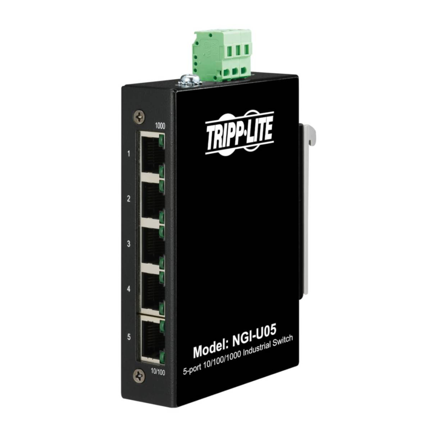
Unmanaged DIN-Mountable
Industrial 10/100/1000
Gigabit Ethernet Switches
Models: NGI-U05, NGI-U08, NGI-U16
Este manual está disponible en español en la página de Tripp Lite:
Ce manuel est disponible en français sur le site Web de Tripp Lite :
Русскоязычная версия настоящего руководства представлена на
веб-сайте компании Tripp Lite по адресу: tripplite.com
Dieses Handbuch ist in deutscher Sprache auf der Tripp Lite-Website
WARRANTY REGISTRATION
Register your product today and be automatically entered to win an ISOBAR
surge protector in our monthly drawing!
1111 W. 35th Street, Chicago, IL 60609 USA • tripplite.com/support
Copyright © 2021 Tripp Lite. All rights reserved.
tripplite.com
tripplite.com
verfügbar: tripplite.com
tripplite.com/warranty
1
®

Advertisement

Table of Contents
loading

Summary of Contents for Tripp Lite NGI-U05

  • Page 1 Models: NGI-U05, NGI-U08, NGI-U16 Este manual está disponible en español en la página de Tripp Lite: tripplite.com Ce manuel est disponible en français sur le site Web de Tripp Lite : tripplite.com Русскоязычная версия настоящего руководства представлена на веб-сайте компании Tripp Lite по адресу: tripplite.com Dieses Handbuch ist in deutscher Sprache auf der Tripp Lite-Website verfügbar: tripplite.com...
  • Page 2: Package Contents

    • DIN Rail-Mounting Clip (Preinstalled) • Wall-Mount Mask (Preinstalled on NGI-U05 Only) • Owner’s Manual Product Features • 5 (NGI-U05), 8 (NGI-U08) or 16 (NGI-U16) auto-negotiable 10/100/1000 Mbps RJ45 ports • Supports 10/100/1000Base-T, Full Duplex and Auto MDI/MDI-X crossover function •...
  • Page 3: Optional Accessories

    Note: Contact tripplite.com/support for information on availability of enhanced functionality. • Preinstalled durable rail clip mounts firmly to any standard 35 mm DIN rail Note: Only NGI-U05 is both DIN and wall mountable. • Simple plug-and-play installation and operation with no configuration required Optional Accessories •...
  • Page 4: Product Overview

    Product Overview NGI-U05 5-Port Unmanaged Industrial Gigabit 10/100/1000 Ethernet Switch, Plug and play – Din and Wall Mountable 1000 Mbps Power Grounding Screw 10/100 Top View Front View Side View NGI-U08 8-Port Unmanaged Industrial Gigabit 10/100/1000 Ethernet Switch, Plug and play – DIN Mountable...
  • Page 5 Product Overview NGI-U16 16-Port Unmanaged Industrial Gigabit 10/100/1000 Ethernet Switch, Plug and Play, DIN Mountable DIN Rail 1000 Mbps Grounding Screw Power Input Terminal Block Grounding Screw LNK/ACT Top View Front View...
  • Page 6 DIN-Rail Mounting/Dismounting Instructions ATTENTION: Switch models NGI-U05, NGI-U08 and NGI-U16 are open-type devices and shall be DIN- rail mounted. Model NGI-U05 may be wall mounted (optional) in cabinet or enclosure. The ambient temperature should not exceed 167°F (75°C). Mounting the Switch Place the NGI-Series switch on the DIN rail from above using the slot.
  • Page 7 When mounting the switch, be sure to allow enough space between devices to install the cabling and to ensure proper airflow. Wall-Mounted Mask (NGI-U05 Only) 1. Mount the switch by using mounting holes on the wall at the appropriate places.
  • Page 8 DIN Mounting/Dismounting Instructions 2. The switch can be wall mounted either vertically or horizontally. Note: Horizontal mounting is not evaluated by UL. Mounting direction with screw Mounting direction with screw Straight Direction Horizontal Direction Installation Installation (Horizontal direction is not evaluated by UL)
  • Page 9: Wiring Requirements

    Wiring Requirements WARNING: Safety measures should be taken before connecting the power cable. Turn off the power before connecting modules or wires. The correct power supply voltage is listed on the product label. Check the voltage of your power source to make sure you are using the correct voltage.
  • Page 10 Wiring Requirements Wiring Power Input NGI-U05 with 3-Pin Terminal Block Check the polarity while connecting. Top view of the Terminal Block is shown in the figure below: Power Input Terminals Grounding Terminals Power Grounding Screw...
  • Page 11 Wiring Requirements To insert power wire and connect the 9~48VDC at a maximum of 0.5A DC power to the power terminal block, follow these steps: • Use a flat-head screwdriver to loosen the wire-clamp screws. • Insert the negative/positive DC wires into the ( - / + ) terminals, respectively.
  • Page 12 Wiring Requirements CAUTION: • Use copper conductors only. • Wiring cable temperature should support at least 220°F (105°C). • Tighten the wire to a torque value of 5 lb.-in. • The wire gauge for the terminal block should range between 12 and 24 AWG.
  • Page 13 Wiring Requirements Wiring the Relay Contact (ALM) – only for device with 6-pin terminal block The NGI-U08 (device with 6-pin terminal block) has one set of relay alarm output. This relay contact uses two contacts of the terminal block on the NGI-U08 top panel. The two contacts of the 6-pin terminal block connector are used to detect user-configured events.
  • Page 14 Wiring Requirements DIP Switch Settings The switch supports an “Alarm Relay Output” function. You can connect an alarm light or a buzzer. When events occur that enabled by the DIPs, the switch will operate the relay ON to enable the alarm light or a buzzer. The load can be an “alarm light”...
  • Page 15 Wiring Requirements NGI-U08 DIP Switches 10 P8 ON: Primary power alarm reporting is enabled OFF: Primary power alarm reporting is disabled ON: Redundant power alarm reporting is enabled OFF: Redundant power alarm reporting is disabled ON: Port 1 link alarm reporting is enabled OFF: Port 1 link alarm reporting is disabled ON: Port 2 link alarm reporting is enabled OFF: Port 2 link alarm reporting is disabled...
  • Page 16 Wiring Requirements NGI-U16 with 2-Pin 12~48VDC Terminal Block You can use “PWR” for power input. Top view of the Terminal Block Terminal Block is shown in the figure at right. CAUTION: • Use copper conductors only. • Wiring cable temperature should support at least 220°F (105°C). •...
  • Page 17 Ports 1 through 5, 8 or 16 on the switch support Fast Ethernet, as well as Gigabit Ethernet (10/100/1000Base-T ports). All the RJ45 ports on the NGI-U05 and NGI-U08 support auto- negotiation and Auto MDI/MDI-X to eliminate the need for crossover cabling.
  • Page 18: Led Indicators

    LED Indicators NGI-U05 Illuminated Power On by terminal block PWR (Green) Terminal block PWR failed or is not available Illuminated Link speed at 1000 Mbps 1000 Blinking Data is transmitting/receiving (Green) Link speed at 10/100 Mbps or link failed Illuminated...
  • Page 19 LED Indicators NGI-U08 Illuminated Power On by terminal block PWR or DC jack Terminal block PWR/DC jack failed or is not (Green) available Illuminated Power on by terminal block RPS (Green) Terminal block RPS failed or is unavailable Illuminated PWR/RPS failed or unavailable (Red) No power or DIP function is disabled Illuminated...
  • Page 20 LED Indicators NGI-U16 Illuminated Power is supplied to switch (Green) Power off or failed Illuminated Link speed at 1000 Mbps 1000 (Green) Link speed at 10/100 Mbps Illuminated Ethernet link-up LNK/ACT Blinking Data is transmitting/receiving (Green) Port disconnected or link failed ATTENTION: This device complies with Part 15 of the FCC rules.
  • Page 21: Specifications

    Specifications Model NGI-U05 NGI-U08 NGI-U16 Power Input Voltage Single power input Dual power inputs Single power input 9~48VDC/0.5A 9~57VDC/1A 12~48VDC/1.5A Connection 3-pin terminal block 6-pin terminal block 2-pin terminal block Reverse Polarity Present Present Present Protection Power Consumption (System Only)
  • Page 22 Specifications Model NGI-U05 NGI-U08 NGI-U16 Alarm Relay Output 1 Alarm relay output for power loss and port link down Environmental Operating -40°F to 167°F -40°F to 167°F -40°F to 167°F Temperature (-40°C to 75°C) (-40°C to 75°C) (-40°C to 75°C) Storage -40°F to 185°F...
  • Page 23: Warranty And Product Registration

    Visit tripplite.com/warranty today to register your new Tripp Lite product. You’ll be automatically entered into a drawing for a chance to win a FREE Tripp Lite product!* *No purchase necessary. Void where prohibited. Some restrictions apply. See website for details.
  • Page 24 • Consult the dealer or an experienced radio/TV technician for help. Any changes or modifications to this equipment not expressly approved by Tripp Lite could void the user’s authority to operate this equipment. Use of this equipment in life support applications where failure of this equipment can reasonably be expected to cause the failure of the life support equipment or to significantly affect its safety or effectiveness is not recommended.

This manual is also suitable for:

Ngi-u08Ngi-u16

Table of Contents