Table of Contents
Advertisement
Quick Links
Lokdecoder für Wechselstrommotoren
Locomotive Decoder for AC engines
Décodeur pour locomotive avec moteur alternatif
Locdecoder voor wisselstroommotoren
Lokdecoder für Gleichstrommotoren
Locomotive Decoder for DC engines
Décodeur pour locomotive avec moteur continu
Locdecoder voor gelijkstroommotoren
LD-W-3
Motorola-Format
Motorola-Format
Format-Motorola
Motorola-format
Art.-Nr. 22-01-051
LD-G-3
Motorola-Format
Motorola-Format
Format-Motorola
Motorola-format
Art.-Nr. 22-01-052
n
n
n
n
n
n
n
n
n
n
Anleitung
n
Manual
n
Mode d´emploi
n
Handleiding
n
n
n
Advertisement
Table of Contents

Related Manuals for tams elektronik LD-W-3


Summary of Contents for tams elektronik LD-W-3
- Page 1 LD-W-3 Lokdecoder für Wechselstrommotoren Motorola-Format Locomotive Decoder for AC engines Motorola-Format Décodeur pour locomotive avec moteur alternatif Format-Motorola Locdecoder voor wisselstroommotoren Motorola-format Art.-Nr. 22-01-051 LD-G-3 Anleitung Lokdecoder für Gleichstrommotoren Manual Motorola-Format Locomotive Decoder for DC engines Mode d´emploi Motorola-Format Décodeur pour locomotive avec moteur continu...
- Page 2 © 03/2003 Tams Elektronik GmbH Alle Rechte, insbesondere das Recht der Vervielfältigung und Verbreitung sowie der Übersetzung vorbehalten. Vervielfältigungen Reproduktionen jeglicher Form bedürfen schriftlichen Genehmigung Deutsch durch die Tams Elektronik GmbH. English Technische Änderungen vorbehalten. Français © 03/2003 Tams Elektronik GmbH rights reserved.
-
Page 3: Table Of Contents
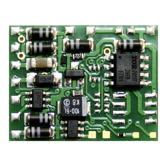
Manufacturer's note Certification Conditional warranty Fig. 1: Connections LD-G-3 Fig. 2: Connections LD-W-3 Fig. 3: Connection of the lighting to locomotive ground Fig. 4: Circuit Diagram (Pages I to II in the centre of this handbook are removeable.) Page 22... -
Page 4: How To Use This Manual
The module can be used according to the specifications of this manual. It is designed for the mounting in a model railway locomotive with d.c. motor (LD-G-3) resp. a.c. motor (LD-W-3). It evaluates the Motorola format data sent by the digital central unit to its address. -
Page 5: Safety Instructions
English LD-G-3 / LD-W-3 Safety instructions Mechanical hazards Cut wires can have sharp ends and can cause serious injuries. Watch out for sharp edges when you pick up the PCB. Visibly damaged parts can cause unpredictable danger. Do not use damaged parts: recycle and replace them with new ones. - Page 6 LD-G-3 / LD-W-3 English Fire risk Touching flammable material with a hot soldering iron can cause life- threatening fire, burns and toxic smoke. Connect your soldering iron or soldering station only when actually needed. Use the correct soldering iron or station and never leave a hot soldering iron or station unattended.
-
Page 7: Emc Declaration
English LD-G-3 / LD-W-3 EMC declaration This product is developed in accordance with the European standards EN 55014 and EN 50082-1, tested corresponding to the EC - directive 89/336/EWG (EMVG of 09/11/1992, electromagnetic tolerance) and meets legal requirements. To guarantee the electromagnetic tolerance you must take the following precautions: §... -
Page 8: Operation Overview
LD-G-3 / LD-W-3 English Operation overview The decoder is designed for operation in Motorola I or II format and can be adjusted to one of 255 adresses. It evaluates the digital data sent by the central unit to its address and transmitts it to the locomotive. -
Page 9: Technical Specifications
English LD-G-3 / LD-W-3 Shunting gear The auxiliary function F4 allows you to switch into the shunting gear mode. In the shunting gear mode the velocity of all speed levels is reduced to ca. 50 % compared to the standard velocity. -
Page 10: Safe And Correct Soldering
LD-G-3 / LD-W-3 English § a soldering iron stand with tip-cleaning sponge § a small side cutter and wire stripper § an electronic soldering iron (max. 30 Watt) with a fine tip § tin solder (0,5 mm. diameter) § wire (diameter: > 0,05 mm²) -
Page 11: Performing A Visual Check
English LD-G-3 / LD-W-3 Performing a visual check Damaged materials can cause injury. Parts damaged during transit can also be dangerous.Check the module for damage, missing parts or poor soldering. If you find damage, return the module for exchange. Mounting the locomotive decoder Open the locomotive housing. - Page 12 LD-G-3 / LD-W-3 English If the lamps are already connected with one side to locomotive ground, the connection is complete. If not, connect the second side of the lamps to the return conductor (point X1 resp. X6). Caution: The return conductor for all functions (point X1 resp. X6) must under no circumstances be connected to locomotive ground.
-
Page 13: Programming The Locomotive Decoder
English LD-G-3 / LD-W-3 Fixing the locomotive decoder After completing all connections fix the locomotive decoder with double- sided adhesive tape, for example. Using an NEM 652 interface connector Some locomotives already have an NEM 652 interface connector mounted. Using a convenient connecting plug you save disconnecting the connections and you do not need to solder at the locomotive. - Page 14 LD-G-3 / LD-W-3 English Online-programming In the programming mode, the starting velocity, the maximum velocity as well as the acceleration and brake delay are tested and directly saved. For that reason you need an isolated oval section of track for programming.
- Page 15 English LD-G-3 / LD-W-3 1. Programming the locomotive address After accessing the programming mode enter the present or the new locomotive address. It is not necessary to enter the old address if you intend to enter a new locomotive address. Confirm the input by switching on the function "function".
-
Page 16: Reset
LD-G-3 / LD-W-3 English Skipping single menu points If you want to skip single menu points set the speed control knob to "0", and switch the function "function" on and off once. The decoder retains the driving characteristics that have already been saved. The decoder confirms the finishing of a menu point by flashing the front lamp of the locomotive. -
Page 17: Faq
English LD-G-3 / LD-W-3 Switching the shunting gear The shunting gear can be switched on and off via the auxiliary function F4. In the shunting gear mode the velocity of all speed levels is reduced to ca. 50 % compared to the standard velocity. The change of the setting takes effect immediately. -
Page 18: Manufacturer's Note
LD-G-3 / LD-W-3 English § The locomotive lighting does not correspond to its direction of travel. Possible cause: The forward and backward light connections have been exchanged. à Check the connections. Possible cause: The connections of the motor to the points X10 and X11 have been exchanged. -
Page 19: Conditional Warranty
English LD-G-3 / LD-W-3 Conditional warranty This product is guaranteed for two years. The warranty includes free repair if the problem is due to material failure or incorrect assembly of the module by us. We guarantee the quality of the components. - Page 20 LD-G-3 / LD-W-3 LD-G-3 / LD-W-3 Fig. 1: Fig. 3: Anschluß LD-G-3 Anschluß der Beleuchtung Connections LD-G-3 an Lokmasse Connexion LD-G-3 Connection of the lighting Aansluiten LD-G-3 to locomotve ground Raccordement de l´éclairage via le châssis de la loco Verbining van de verlichting met de locmassa Fig.
- Page 21 LD-G-3 / LD-W-3 LD-G-3 / LD-W-3 Fig. 4: Schaltplan - Circuit diagram - Schéma de principe - Schakelschema Seite - Page - Page - Pagina II Seite - Page - Page - Pagina II...
- Page 22 Actuele informatie en tips: http://www.tams-online.de Garantie und Service: Warranty and service: Garantie et service: Garantie en service: Tams Elektronik GmbH Rupsteinstraße 10 D-30625 Hannover fon: ++49 (0)511 / 55 60 60 fax: ++49 (0)511 / 55 61 61 e-mail: modellbahn@tams-online.de...
Need help?
Do you have a question about the LD-W-3 and is the answer not in the manual?
Questions and answers