Table of Contents
Advertisement
Quick Links
Advertisement
Table of Contents

Related Manuals for RTS MCII-e


Summary of Contents for RTS MCII-e
-
Page 1: User Manual
MCII-e System Controller Card User Manual 9350-7734-000 Rev A May/2005... - Page 2 Telex reserves all patent, proprietary design, manufacturing, reproduction, use and sales rights thereto, and to any article disclosed therein, except to the extent rights are expressly granted to others. COPYRIGHT NOTICE Copyright 2005 by Telex Communications, Inc. All rights reserved. Reproduction, in whole or in part, without prior written per- mission from Telex is prohibited. WARRANTY NOTICE See the enclosed warranty card for further details.
-
Page 3: Table Of Contents
Configuring the MCII-e ... 17 System Requirements ... 18 Ethernet Setup for MCII-e System Controller ... 18 Set the IP Address for the MCII-e System Controller ...18 Download Firmware for the MCII-e System Controller ... 21 Chapter 3 Accessories... 25 Accessories ... -
Page 5: Introduction
In this chapter • Introduction • Features • Specifications • Reference View - Front Card • Reference View - Back Card • DIP Switches • Connector Pin-outs CHAPTER 1 Introduction... -
Page 6: Introduction
Adding Ethernet connectivity between the ADAM Intercom and the PC running AZedit, the new controller can support up to 35 simultaneous AZedit sessions (32 using Ethernet and up to 3 using serial ports). Using a pair of MCII-e controller cards will provide full redundancy with seamless automatic change-over upon failure. -
Page 7: Specifications
Specifications Controls: Reset push-button switch, general indicators, an LED module for advanced monitoring features and for gathering additional card information. Specifications Power 7.5W/ 1.5A @ 5V Physical 5.687” (144.45mm) W x 11.024” (280.01 mm) L Connectors SCSI connector via backcard RJ-45 Ethernet via backcard Miscellaneous 4 Mbytes of Code Flash... -
Page 8: System Diagram
Introduction System Diagram AZedit System Diagram - MCII-e Master Controller Figure 1. -
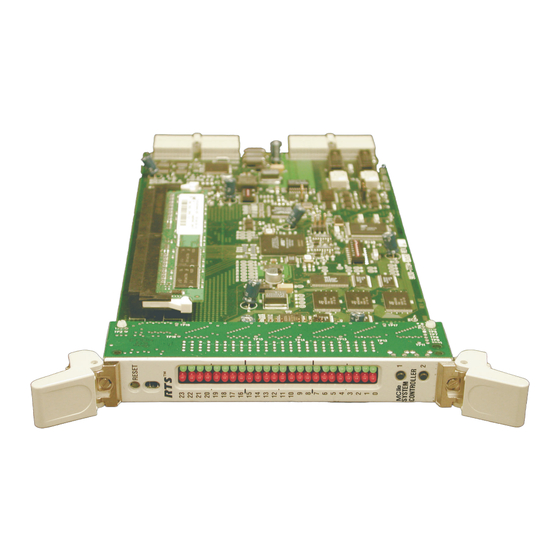
Page 9: Reference View - Front Card
Reference View - Front Card Reference View - Front Card Jumper Settings Programming Use ONLY! J801 - Pins 1 & 2 must be shorted. Pins 3 & 4 must be shorted. MCII-e System Controller Card Board view. Figure 2. - Page 10 Introduction LED Descriptions for the MCII-e Figure 3.
-
Page 11: Reference View - Back Card
Reference View - Back Card Reference View - Back Card Back Card Figure 4. DIP Switches Closed Open Dip Switch SE02 Figure 5. DIP Switch 1: Debug Only! Must be in OPEN position. DIP Switch 2: Sets the baud rate for the AZedit serial connection via J1. By default, AZedit is set for COM 1 and 38,400 kbps (38.4K). - Page 12 Introduction DIP Switches 3, 4, and 5: DIP Switch 6: DIP Switch 7: DIP Switch 8: Warning: DIP Switches 1, 6, and 8 should always be left in the OPEN position. These are reserved for debugging and can have unintended consequences. baud rate set in AZedit must match the baud rate setting of the Master Controllers in ADAM.
-
Page 13: Connector Pinouts
Connector Pinouts Connector Pinouts 68-pin Master Controller 68-pin Master Controller AZedit #1 J-1 of XCP-ADAM-MC Assignment 2W RS485 TX/RX- RS232C RX RS232C TX RS422 TX- Ground Ground RS422 TX+ RS485 TX/RX+ Trunking System J-2 of XCP-ADAM-MC Assignment 2W RS485 TX/RX- Ground RS232C RX Not Used... - Page 14 Introduction UIO-256/PAP/LCP 68-pin Master J-3 of Controller XCP-ADAM-MC General Purpose 68-pin Master J-4 of Controller XCP-ADAM-MC Assignment 2W RS485 TX/RX- Ground Not Used Not Used RS422 TX+ RS485 TX/RX+ Ground Not Used RS422 TX- Assignment 2W RS485 TX/RX- Ground Not Used Not Used RS422 TX+ RS485 TX/RX+...
- Page 15 Connector Pinouts General Purpose 68-pin Master Controller XCP-ADAM-MC General Purpose / Bus Exp. 68-pin Master Controller XCP-ADAM-MC J-5 of Assignment 2W RS485 TX/RX- Ground Not Used Not Used Not Used RS485 TX/RX+ Ground Not Used Not Used J-6 of Assignment 2W RS485 TX/RX- Ground Not Used...
- Page 16 Introduction General Purpose / Bus Exp. 68-pin Master J-7 of Controller XCP-ADAM-MC General Purpose / Bus Exp. 68-pin Master J-8 of Controller XCP-ADAM-MC Assignment 2W RS485 TX/RX- Ground Not Used Not Used Not Used RS485 TX/RX+ Ground Not Used Not Used Assignment 2W RS485 TX/RX- Ground...
- Page 17 Connector Pinouts AZedit #2 68-pin Master Controller XCP-ADAM-MC AZedit #3 68-pin Master Controller XCP-ADAM-MC J-9 of Assignment 2W Not Used Ground RS232C RX Not Used Not Used Not Used Ground RS232C TX Not Used J-10 of Assignment 2W Not Used Ground RS232C RX Not Used...
- Page 18 Introduction General Purpose Assignment MI (0) MI (1) MI (2) MI (3) MI (4) MI (5) MI (6) MI (7) Ground Ground Ground Ground Ground MO (0) MO (1) MO (2) MO (3) MO (4) MO (5) MO (6) MO (7) Ground Ground Ground...
-
Page 19: Configuring The Mcii-E
In this chapter • System Requirements • Ethernet Setup for the MCII-e System Controller • Download Firmware for the MCII-e System Controller Configuring the MCII-e CHAPTER 2... -
Page 20: System Requirements
Periph-IIe, requires DBX v1.14.0 or later NOTE: Field upgrade of DBX will requires Boot Code upgrade to version 0.0.3. If the Boot Code is not upgraded, the DBX card will not work with the MCII-e. Refer to DBX Boot Code Upgrade (pn 38110-472. - Page 21 From the Option menu, select Ethernet Setup. The Ethernet Setup screen appears. In the IP Address field, enter the IP Address for the current MCII-e System Controller. In the Network Mask field, enter the Network Mask number for the current MCII-e Sys- tem Controller.
- Page 22 The Communication screen appears In the Connection area, select the Network radio button. In the IP Address field, either enter the MCII-e IP Address you wish to connect with, or click the Search button devices. If multiple units are on the network, each will appear in the list.
-
Page 23: Download Firmware For The Mcii-E System Controller
Download Firmware for the MCII-e System Controller Select the MCII-e System Controller you wish to work with. Click OK. The Communications screen closes. The IP Address is configured in AZedit for the MCII-e System Controller. Download Firmware for the MCII-e System Controller WARNING: The following procedure will cause one or more brief disruptions in intercom communications. - Page 24 NOTE: If there is any disruption in the communications link during the download, you will get an error message. In this case, repeat the download. When the file has been completely downloaded, the MCII-e System Controller will begin processing the update.
- Page 25 Download Firmware for the MCII-e System Controller...
- Page 26 Configuring the MCII-e...
-
Page 27: Accessories
In this chapter • Accessories • AZedit • UIO-256 • • • General Purpose CHAPTER 3 Accessories... -
Page 28: Accessories
Accessories Accessories figure 1. XCP-ADAM-MC. NOTE: AZedit sessions are only enabled on J9 or J10 when the advanced communication boxes are enabled from “communications” screen and the correct baud rates are config- ured. XCP-ADAM-MC Master Controller Breakout Panel The XCP-ADAM-MC Breakout Panel allows many different peripherals to be connected to the master controller of an ADAM Intercom System, such as AZedit, trunking systems, UIOs, PAPs, LCPs, GPI/Os, etc. -
Page 29: Trunking Systems
Accessories has the capability to load pre-set configuration files, which means configurations saved to a disk can be uploaded to the “live” application at anytime, without interruption. The XCP-ADAM-MC breakout panel has three DB-9 connectors that can be used to connect to AZedit (AZedit #1, #2, and #3). - Page 30 Accessories...
-
Page 31: Trunking And The Mcii-E System
Trunking and the MCII-e System In this chapter • Enable Trunk Support for MCII-e System Controller Card • Connect MCII-e to the Trunk Master (Data) • Configure TrunkEdit and AZedit to Communicate with the MCII-e System Controller Card CHAPTER 4... -
Page 32: Trunking And The Mcii-E System Controller
To trunk the MCII-e System Controller Card, do the following: ENABLE TRUNK SUPPORT IN AZEDIT From the AZedit main menu, select Options. - Page 33 CONNECT THE MCII-e TO THE TRUNK MASTER (DATA) To connect MCII-e to the Trunk Master, do the following: Connect the MCII-e System Controller Card data connector to one of the eight DB-9 con- nections on the ICP-2000. CONFIGURE THE TRUNKMASTER TO COMMUNICATE WITH...
- Page 34 When you are finished, click the Send button to send the changes to the Trunk Master. When the changes are sent to the Trunk Master, the MCII-e connects to the Trunk Mas- ter and uploads the remote ports. Once the MCII-e has uploaded this data, it sends its port alphas to the Trunk Master.
- Page 35 Trunking and the MCII-e System Controller Defining the trunk line shows where a trunk line begins and ends, as well as shows the audio connections between frames. To define trunk lines, do the following: Open TrunkEdit. In the left navigation, open the Trunk slide screen.
- Page 36 Trunking and the MCII-e System...
Need help?
Do you have a question about the MCII-e and is the answer not in the manual?
Questions and answers