
Related Manuals for SystemAir fantech DPV 22.2


Summary of Contents for SystemAir fantech DPV 22.2
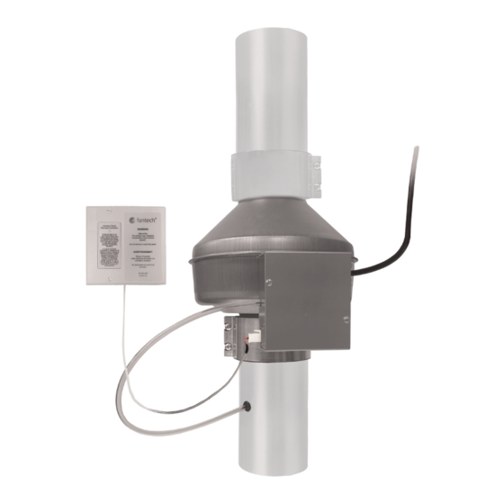
- Page 1 Installation, Operations, and Maintenance instruction DPV 22.2 Dryer Exhaust Duct Power Ventilator...
-
Page 2: Table Of Contents
Table of contents 1 Introduction ............. 1 Product Description ........1 Intended Use..........1 Document Description ........1 Fantech Warranty........... 1 Product Overview ........... 2 Type Designation ........... 2 2 Safety ..............2 Safety definitions..........2 Safety Instructions.......... 2 Personal protective equipment ......3 3 Installation .............. -
Page 3: Introduction
Introduction Fantech Warranty Product Description This product is specifically designed to assist a single residen- tial dryer (gas or electric) in overcoming dryer performance loss caused by long or restrictive duct systems. Dryer Exhaust Duct Power Ventilators (DEDPVs) are different from the term dryer booster because this product has to comply with strict safety requirements. -
Page 4: Product Overview
Product Overview Safety Safety definitions Warnings, cautions and notes are used to point out specially important parts of the manual. Warning If you do not obey these instructions, there THIS CLOTHES is a risk of death or injury. DRYER INSTALLATION INCORPORATES A DRYER EXHAUST SOLUTION Steady blue light when dryer is... -
Page 5: Personal Protective Equipment
• Do not install the product in duct systems where the equiva- Installation lent duct length is less than 25 feet (7.6 meters). • To prevent damage to the dryer or to the product, do not in- To Do Before the Installation stall the DPV 22–2, #75104 within 5 linear feet (1.5 linear meters) or further than 40 linear feet (12 linear meters) from Caution... -
Page 6: How The Pressure Sensor Switch Operates
If installer chooses to mount indicator panel in a single gang junction box (by others), it should not be installed in a box that has line voltage wiring or devices. 3.1.4 How the Pressure Sensor Switch Operates The product contains a positive pressure sensing switch that recognizes airflow velocity and activates the product from an in- dependent electrical circuit. - Page 7 On the opposite end of the control box, position the bracket onto the product. Make a mark through the middle holes of the bracket onto the product. Using the marks for guidance, drill two (2) 3/32" (2mm) pi- lot holes in the product. Using two (2) self tapping 1/2 inch (13mm) screws pro- vided, attach product to the mounting bracket.
- Page 8 3.2.1.4 To Position the Pressure Switch Note: The figure that follows shows how to correctly position the pressure switch on horizontal, angled, or vertical duct work. Note: On both ends of the cleanout ducts, leave 0.06 inches (1.5mm) of clearance to mate the ducts. Move the two (2) FC Mounting Clamps onto both ends of the cleanout ducts.
- Page 9 Tubing 1/2 inch (13mm) Grommet Duct Wall 1/4 inch (6mm) maximum 3.2.1.6 To Connect the Indicator Panel 3.2.1.7 To Install the Indicator Panel Cable to the Product Caution Connect the two (2) position connector at the end of the Install the indicator panel near the dryer so 50–foot (15 meter) indicator panel cable to the receptacle it can be clearly seen.
-
Page 10: Wiring Diagrams
Medium-sized Screw Decora Plate Indicator Panel 2 gang mount box (not included) Large-sized Screw Adjustment Plate Small-sized Screw Wiring diagrams Wiring Legend for Diagram English Terminology Meaning 120VAC Power Cord 120 Voltage Alternating Current Power Supply BLACK (BLK) (Line) Black (Line) WHITE (WHT) (Neutral) White (Neutral) Green (GRN) (Ground) - Page 11 Blk — Motor Wire (Line Voltage) Black — Motor Wire (Line Voltage) Brn — Motor Wire (Capacitor) Brown — Motor Wire (Capacitor) DB20 Pressure Module DB20 Pressure Module Power Wire Motor Line Neutral 1 Neutral 2 High Voltage 1 High Voltage 2 High Voltage 3 DPV22-2 Fan Assembly Thermal Cuto...
-
Page 12: To Wire The Panel
4.1.1 To Wire the Panel On the end of the 50–foot (15.2 meter) cable with stripped wires, connect the red wire to the positive (+) position of the terminal block located on the indicator panel. From that same end of the cable, connect the black wire to the negative (-) position of the terminal block located on the indicator panel as shown in the wiring diagrams. -
Page 13: Troubleshooting
Troubleshooting Note: If the panel LED flashes or does not illuminate when the dryer is on, see the below table for error indication and likely sources of the problem. If the product shows an error other than what is listed, or if these help topics do not solve the problem, please contact Fantech technical support for further assistance. -
Page 14: Maintenance
After the dryer starts, the product will start to operate ten Maintenance (10) seconds after the dryer has started. Warning Note: Set the service disconnect switch in the The indicator LED will also illuminate during this time. OFF position before you do maintenance unless the instructions tell you differently. -
Page 15: Technical Data
Technical data Product Dimensions Note: Dimensions are given in inches (mm). 9–11/16 DPV 22–2, 2 (51) 4 (102) 9/16 (14) 10 (254) 4 (102) 1/32 (0.8) (246) #75104... - Page 16 last page Canada Latin America (800) 747 1762 (800) 565 3548 +52 55 1328 7328 support@fantech.net support@fantech.net support@fantech.net © Copyright Fantech All rights reserved Fantech reserves the rights to alter their products without notice. This also applies to products already ordered, as long as it does not affect the previously agreed specifications.
Need help?
Do you have a question about the fantech DPV 22.2 and is the answer not in the manual?
Questions and answers