Sinope - TH1123ZB-G2, TH1124ZB-G2 Smart Thermostat for Electric Heating Manual
- Installation manual (2 pages)
Advertisement
- 1 DEVICE OVERVIEW
- 2 TECHNICAL SPECIFICATIONS
- 3 INSTALL YOUR THERMOSTAT
- 4 ADD YOUR THERMOSTAT TO THE GT130 GATEWAY AND NEVIWEB
- 5 CONNECT YOUR THERMOSTAT TO THE GT130 GATEWAY OR A COMPATIBLE ZIGBEE SYSTEM
- 6 DISCONNECT YOUR THERMOSTAT FROM THE GT130 GATEWAY OR A COMPATIBLE ZIGBEE SYSTEM
- 7 USER SETTINGS
- 8 3-year limited warranty
- 9 Documents / Resources
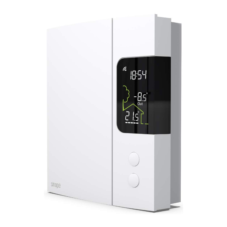
DEVICE OVERVIEW

Time
(provided by the gateway)
Secondary display: Set point [Set) or outside temperature [Out]
TECHNICAL SPECIFICATIONS
Operating voltage: 120 / 208 / 240 Vac, 60 Hz
- TH1123ZB-G2 Thermostat
Maximum load:
12.5 A / 3000 W @ 240 Vac
12.5 A / 1500 W @ 120 Vac
- TH1124ZB-G2 Thermostat
Maximum load:
16.7 A / 4000 W @ 240 Vac
16.7 A / 2000 W @ 120 Vac
Minimum load: Baseboard, convector and radiant ceiling
2 A / 500 W @ 240 Vac
2 A / 250 W @ 120 Vac
Fan-forced convector
4.16 A / 1000 W @ 240 Vac
4.16 A / 500 W @ 120 Vac
Resistive load only
Setpoint range: 5 ˚C to 30 ˚C (41 ˚F to 86 ˚F)
Display range: 0 ˚C to 50 ˚C (32 ˚F to 99 ˚F)
Resolution: ± 0.5 ˚C (± 1 ˚F)
Storage: -20 ˚C to 50 ˚C (-4 ˚F to 122 ˚F)
Operation: 0 ˚C to 50 ˚C (32 ˚F to 122 ˚F)
Protocol: Zigbee 3.0
Frequency: 2.4 GHz
Transmission power: +20 dBm
Receiver sensitivity: -108 dBm
Compatible with an electric heating system such as:
- Baseboard heater [short cycle]
- Convector [short cycle]
- Fan-forced convector [long cycle)
- Radiant ceiling heating

The installation of this thermostat must be performed by a certified electrician and comply with the national and local electrical codes and regulations.
Special CO/ ALR solderless connectors must be used when connecting with aluminum conductors.
INSTALL YOUR THERMOSTAT
- Make sure that the breakers for your heating system are off at the main electrical panel to avoid any risk of electric shock.
![]()
- Unlock and lift the thermostat cover.

- Use the connectors provided to connect the thermostat wires to the wires in the electrical box.

Two-wire installation

Four-wire installation
![warning]() Note: The wires of this thermostat are non-polarized.
Note: The wires of this thermostat are non-polarized. - Replace the cover and lock
![]()
- Power up the thermostat.
![]()


 Note: The wires of this thermostat are non-polarized.

Make sure to firmly tighten the wire connectors for a secure connection. A loose connection can be a fire hazard.

To install wire connectors, you must:
- Insert the two wires into the wire nut so that their copper ends are parallel.
- Turn the wire connector clockwise until there is strong tension.
- Pull on the threads to make sure they are secure, leaving no gaps between them.
* If the threads seem to come loose, repeat the process.
* Improperly installed electrical wires could burn the wire connectors.
ADD YOUR THERMOSTAT TO THE GT130 GATEWAY AND NEVIWEB
- If you do not have an account yet, download the Neviweb app for iOS or Android to create an account and add your device.
![]()
Get the app
![]()
![www.apple.com]()
![play.google.com]()
- Tap
![]() , then select "Add Device".
, then select "Add Device". - Follow the steps of the installation wizard.


 , then select "Add Device".
CONNECT YOUR THERMOSTAT TO THE GT130 GATEWAY OR A COMPATIBLE ZIGBEE SYSTEM
- Initiate the connectivity session by pressing the RF signal button
![]() on the GT130 gateway. The indicator light will start flashing.
on the GT130 gateway. The indicator light will start flashing.
Compatible Zigbee gateway: refer to the installation guide for the latter.

- Connect your thermostat to the network by pressing the
![]() and
and ![]() buttons briefly and simultaneously.
buttons briefly and simultaneously.
On the thermostat display:![]()
Blinks: Connecting
Remains lit: Connected
If the connectivity fails, the![]() symbol will disappear from the display. Refer to our Website to troubleshoot the unit.
symbol will disappear from the display. Refer to our Website to troubleshoot the unit.

- Connect all your devices the same way, by going to the next closest device.
![]()
- When all your devices are connected, close the connectivity session of your GT130 gateway or your compatible Zigbee gateway.

 on the GT130 gateway. The indicator


DISCONNECT YOUR THERMOSTAT FROM THE GT130 GATEWAY OR A COMPATIBLE ZIGBEE SYSTEM
To disconnect your thermostat from the GT130 gateway or a compatible Zigbee hub, press the  and
and  buttons simultaneously for 10 seconds. "FACT RST" will appear on the thermostat's display for approximately 5 seconds.

USER SETTINGS
All of the thermostat's settings can be set through the Neviweb app.
However, if you have not created your account and wish to change the temperature format or the control cycle, you need to:
Get the setpoint to its minimum and hold the button for 10 seconds to access the menu.

Press the  or
or  button to change the setting.
Press the  and
and  buttons simultaneously to save and go to the next parameter.
Continue to press until the end of the list, 10 sec.
| # | Name | Parameter | Display |
| 1 | Units | Temperature scale °C or °F (Default: °C) |  |
| 2 | Cycle | Cycle SHT (short cycle for electric baseboard) FAN (long cycle for fan forced heater) |  |
Neviweb® is a registered trademark of Sinopé Technologies Inc. in Canada and the United States.
Apple and the Apple logo are trademarks of Apple Inc., registered in the U.S. and other countries.
App Store is a service mark of Apple Inc., registered in the U.S. and other countries.
Google Play and the Google Play logo are trademarks of Google Inc.
Transmitter Module IC: 5123A-GM210P / FCC ID:QOQGM210P
This device complies with Industry Canada license exempt RSS standard(s). Operation is subject to the following two conditions:
- this device does not cause interference, and
- this device must accept any interference, including interference that may cause undesired operation of the device.
This equipment has been tested and found to comply with the limits for a Class B digital device, pursuant to part 15 of the FCC Rules. These limits are designed to provide reasonable protection against harmful interference in a residential installation. This equipment generates, uses and can radiate radio frequency energy, and if not installed and used in accordance with the instructions, may cause harmful interference to radio communications. However, there is no guarantee that interference will not occur in a particular installation. If this equipment does cause harmful interference to radio or television reception, which can be determined by turning the equipment OFF and ON, the user is encouraged to try to correct the interference by one or more of the following measures:
- Reorient or relocate the receiving antenna.
- Increase the separation between the equipment and receiver.
- Connect the equipment into an outlet on a circuit different from that to which the receiver is connected.
- Consult the dealer or an experienced radio/TV technician for help.
3-year limited warranty
SINOPÉ TECHNOLOGIES INC. warrants the components of their products against defects in material and workmanship for a 3 year period from the date of purchase, under normal use and service, when proof of purchase of such is provided to the manufacturer. This warranty does not cover any transportation costs that may be incurred by the consumer. Nor does it cover a product that has been improperly installed, misused or accidentally damaged. The obligation of SINOPÉ TECHNOLOGIES INC., under the terms of this warranty, will be to supply a new unit and this releases the manufacturer from paying the installation costs or other secondary charges linked to replacing the unit or the components.
For more information, visit our Website: www.sinopetech.com


Documents / Resources
References
Download manual
Here you can download full pdf version of manual, it may contain additional safety instructions, warranty information, FCC rules, etc.
Download Sinope - TH1123ZB-G2, TH1124ZB-G2 Smart Thermostat for Electric Heating Manual
Advertisement


Need help?
Do you have a question about the TH1123ZB-G2 and is the answer not in the manual?
Questions and answers