Advertisement
Table of Contents
- 1 Technical Specifications
- 2 Warnings
- 3 Install Your Thermostat
- 4 Add Your Thermostat to the GT130 Gateway and Neviweb
- 5 Connect Your Thermostat to the GT130 Gateway or a Compatible Zigbee System
- 6 Disconnect Your Thermostat from the GT130 Gateway or a Compatible Zigbee System
- 7 User Settings
- 8 3-Year Limited Warranty
- Download this manual
TH1123ZB-G2
TH1124ZB-G2
Installation Guide
Smart Thermostat for
Electric Heating
Warnings
The installation of this thermostat must be performed by a certified electrician and comply with the
national and local electrical codes and regulations.
1
Make sure that the
breakers for your
heating system are
off at the main
electrical panel to
avoid any risk of
electrick shock.
Replace the cover
4
and lock
YOUR SMART THERMOSTAT FOR ELECTRIC
HEATING
INSTALL YOUR THERMOSTAT
2
Unlock and lift the
thermostat cover.
5
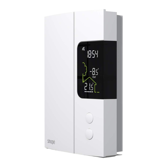
Power up the thermostat.
Out
Gateway connection status
Time
(provided by the gateway)
Secondary display:
Out
Setpoint [Set) or outside
temperature [Out]
Ambient temperature
Heating indicator
Special CO/ ALR solderless connectors must be used
when connecting with aluminum conductors.
Use the connectors provided to connect the thermostat wires
3
to the wires in the electrical box.
Note: The wires of this thermostat are non-polarized.
Two-wire installation
Four-wire installation
TECHNICAL SPECIFICATIONS
Operatlng voltage: 120 / 208 / 240 Vac, 60 Hz
• TH1123ZB-G2 Thermostat
Maximum load:
12.5 A / 3000 W @ 240 Vac
12.5 A / 1500 W @ 120 Vac
• TH1124ZB-G2 Thermostat
Maximum load:
16.7 A / 4000 W @ 240 Vac
16.7 A / 2000 W @ 120 Vac
Minimum load:
Baseboard, convector and radiant ceiling
2 A / 500 W @ 240 Vac
2 A / 250 W @ 120 Vac
Fan-forced convector
4.16 A / 1000 W @ 240 Vac
4.16 A / 500 W @ 120 Vac
Resistive load only
Setpoint range: 5 ˚C to 30 ˚C (41 ˚F to 86 ˚F)
Display range: 0 ˚C to 50 ˚C (32 ˚F to 99 ˚F)
Resolution: ± 0.5 ˚C (± 1 ˚F)
Storage: -20 ˚C to 50 ˚C (-4 ˚F to 122 ˚F)
Operation: 0 ˚C to 50 ˚C (32 ˚F to 122 ˚F)
Protocol: Zigbee 3.0
Frequency: 2.4 GHz
Transmission power: +20 dBm
Receiver sensitivity: -108 dBm
Compatible with an electric heating system such as:
• Baseboard heater [short cycle]
• Convector [short cycle]
• Fan-forced convector [long cycle)
• Radiant ceiling heating
Make sure to firmly tighten the
wire connectors for a secure
connection. A loose connection
can be a fire hazard.
To install wire connectors,
you must:
Insert the two wires into the wire nut so that their
1
copper ends are parallel.
2
Turn the wire connector clockwise until there is
strong tension.
3
Pull on the threads to make sure they are secure,
leaving no gaps between them. * If the threads
seem to come loose, repeat the process.
* Improperly installed electrical wires could burn the wire
connectors.
3/4"
Advertisement
Table of Contents

Related Manuals for Sinope TH1123ZB-G2


Summary of Contents for Sinope TH1123ZB-G2
- Page 1 YOUR SMART THERMOSTAT FOR ELECTRIC TECHNICAL SPECIFICATIONS HEATING Operatlng voltage: 120 / 208 / 240 Vac, 60 Hz • TH1123ZB-G2 Thermostat Maximum load: 12.5 A / 3000 W @ 240 Vac 12.5 A / 1500 W @ 120 Vac TH1123ZB-G2 Gateway connection status •...
- Page 2 ADD YOUR THERMOSTAT TO THE GT130 GATEWAY CONNECT YOUR THERMOSTAT TO THE GT130 AND NEVIWEB GATEWAY OR A COMPATIBLE ZIGBEE SYSTEM Initiate the connectivity session Connect your thermostat to the network by pressing the RF signal button by pressing the buttons briefly If you do not have an account yet, on the GT130 gateway.
Need help?
Do you have a question about the TH1123ZB-G2 and is the answer not in the manual?
Questions and answers