Advertisement
Quick Links
TH1134ZB/HC
Installation Guide
Smart Line Voltage Thermostat
Warnings
The installation of this thermostat must be performed by a certified electrician
and comply with the national and local electrical codes and regulations.
1
Make sure that the
breakers for your
heating system are
off at the main
electrical panel.
Replace the cover
4
and lock.
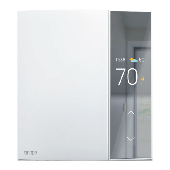
YOUR TH1134ZB HC THERMOSTAT
INSTALL YOUR THERMOSTAT
2
Unlock and lift the
thermostat cover.
5
Power up the thermostat.
Full-color display
Touch-sensor
buttons
Touch control
Special CO/ ALR solderless connectors must be used
when connecting with aluminum conductors.
Use the connectors provided to connect the thermostat wires to the wires in the
3
electrical box. Use the screws to secure the thermostat to the electrical box.
Three-wire installation
White - Neutral/Line 1
Red - Load
Black - Line 2
To control a ductless air conditioner and heat pump unit, you
will need to install an HP6000ZB series controller.
TECHNICAL SPECIFICATIONS
Operatlng voltage: 120 / 208 / 240 Vac, 60 Hz
TH1134ZB/HC Thermostat
Maximum load:
16.7 A / 2000 W @ 120 Vac
16.7 A / 4000 W @ 240 Vac
Resistive load only.
Minimum load:
1.25 A / 300 W @ 240 Vca
1.25 A / 150 W @ 120 Vca
Cooling setpoint range: 61°F to 86°F (16°C to 30°C)
Heating setpoint range: 41°F to 86°F (5°C to 30°C)
Display range: 32°F to 99°F (0°C to 50°C)
Storage: -4°F to 122°F (-20°C to 50°C)
Operation: 32°F to 122°F (0°C to 50°C)
Resolution: ± 0.5°C (± 1°F)
Protocol: Zigbee 3.0
Frequency: 2.4 GHz
Transmission power: +20 dBm
Receiver sensitivity: -108 dBm
Compatible with an electric heating system such as:
• Baseboard heater [short cycle]
• Convector [short cycle]
• Fan-forced convector [long cycle)
• Radiant ceiling heating
• Ductless air conditioners and heat pumps
units with the HP6000ZB series controller
Scan the QR code to view the list
*
of compatible devices or visit
www.support.sinopetech.com/en/1.1.29.3/
Electrical
Make sure to firmly tighten the
panel
wire connectors for a secure
connection. A loose connection
L2
N/L1
can be a fire hazard.
To install wire connectors,
you must:
1
Insert the two wires into the wire nut so that their
copper ends are parallel.
2
Turn the wire connector clockwise until there is
strong tension.
3
Pull on the threads to make sure they are secure,
leaving no gaps between them. * If the threads
seem to come loose, repeat the process.
* Improperly installed electrical wires could burn the wire
connectors.
*
3/4"
Advertisement

Subscribe to Our Youtube Channel
Related Manuals for Sinope TH1134ZB


Summary of Contents for Sinope TH1134ZB
- Page 1 YOUR TH1134ZB HC THERMOSTAT TECHNICAL SPECIFICATIONS Operatlng voltage: 120 / 208 / 240 Vac, 60 Hz TH1134ZB/HC Thermostat Maximum load: 16.7 A / 2000 W @ 120 Vac 16.7 A / 4000 W @ 240 Vac Full-color display Resistive load only.
- Page 2 ADD YOUR THERMOSTAT TO THE GT130 GATEWAY CONNECT YOUR THERMOSTAT TO THE GT130 AND NEVIWEB GATEWAY OR A COMPATIBLE ZIGBEE SYSTEM Connect your thermostat to the Initiate the connectivity session If you do not have an account yet, network by pressing brieffly by pressing the RF signal button download the Neviweb app for iOS or and simultaneously on...
Need help?
Do you have a question about the TH1134ZB and is the answer not in the manual?
Questions and answers