Table of Contents
Advertisement
Quick Links
Advertisement
Table of Contents

Related Manuals for ESAB EASY-WELD SSR 400


Summary of Contents for ESAB EASY-WELD SSR 400
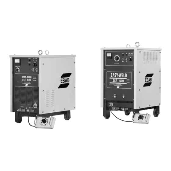
- Page 1 EASY-WELD SSR 400/600 Fully Thyristorised Welding Rectifier (MMA)
- Page 2 EASYWELD SSR 400, SSR 600 FULLY THYRISTORISED MMA WELDING POWER SOURCE Instruction manual Installation, Operation & maintenance...
-
Page 3: Table Of Contents
Contents Page No. SAFETY RATING & ASSEMBLING ACCESSORIES LIST INSTALLATION WELDING OPERATIONS MAINTENANCE & INSPECTION FAULT FINDINGS ELECTRICAL WIRING DIAGRAM 10-11 PCB CHECK POINTS 12-13 WELD DEFECTS AND POSSIBLE CAUSES SPARES LIST... -
Page 4: Safety
SAFETY ___________________________________________________________________________________________________________ Users of ESAB welding equipment have the ultimate responsibility for ensuring that anyone who works on or near the equipment observes all the relevant safety precautions. Safety precautions must meet the requirements that apply to this type of welding equipment. - Page 5 Read and understand the instruction manual before installing or operating. ESAB can provide you with all necessary welding protection and accessories. WARNING Arc welding and cutting can be injurious to yourself and others. Take precautions when welding. Ask for your employer’s safety practices which should be based on manufacturers’ hazard data.
-
Page 6: Rating & Assembling
RATING OF EASYWELD SSR 400, SSR 600 EASY WELD EASY WELD SSR- SSR-400 CHARACTERISTICS INPUT: SUPPLY VOLTAGE, PHASE & 415 V ± 10%, 3 Phase, 50 Hz, AC FREQUENCY MAXIMUM INPUT CURRENT 30 Amps 55 Amps MAXIMUM RATING 21.6 KVA 40 KVA OUTPUT: DC 10-400 A... -
Page 7: Accessories List
ACCESSORY LIST FUSE ELEMENT 1 Piece FUSE ELEMENT 1 Piece INSTALLATION a) Capacity of equipment EASY WELD EASY WELD SSR-400 SSR-600 415 V ± 10% AC INPUT VOLTAGE FREQUENCY & PHASE 50 Hz, 3 PHASE MAXIMUM RATING OF EQUIPMENT 21.6 KVA 40 KVA CAPACITY OF FUSE (B CLASS) 32 Amps HRC... - Page 8 c) Ventilation Adequate ventilation is recommended at the place of installation. For example the following guideline should be followed: − In case of the area is more than 300 square meters (per unit), no ventilation is required, provided the room is not completely air tight. −...
-
Page 9: Welding Operations
WELDING OPERATION Once the installation of the equipment is completed, connect the work Cable to the negative output terminal and the cable end of the electrode holder to the Positive output terminal. These cable connections should be tightened properly to avoid electrical heating due to loose connections. -
Page 10: Maintenance & Inspection
MAINTENANCE & INSPECTION The maintenance and inspection should be carried out only after the main fuse box in the 3-phase AC line is turned OFF or disconnected properly. Maintain and inspect the set regularly as per following guidelines: a) Regular Inspection (Every 3-6 months, depending on operation frequency): Inspection Inspection Point Maintenance Method... -
Page 11: Fault Findings
FAULT FINDING Abnormal Condition Cause Remedy Welding / automatically Control fuse on the front Replace with rated fuse stops and the bottom panel blown WARN LAMP glows The equipment is over In case of the equipment is loaded being operated under duty cycle higher than that of specified and /or higher output current, the bottom... - Page 12 Abnormal Condition Cause Remedy FAN does not rotate Fault in AC input supply. Check the three-phase input while the Power Switch AC supply and current. is ON Open circuit voltage is Fault in 3 phase AC input Check the input line and less than 60 Volts DC supply rectify.
-
Page 13: Electrical Wiring Diagram
WIRING DIAGRAM SSR 400... - Page 14 WIRING DIAGRAM SSR 600...
-
Page 15: Pcb Check Points
Please note that the absolute values may vary with ± 10% and once this testing is over refit the top cover and tighten the top screws properly. In case of abnormalities, please refer to the nearest Area Sales Manager of ESAB INDIA LIMITED with the Serial No. of the equipment & date of purchase. - Page 16 Please note that the absolute values may vary with ± 10% and once this testing is over, refit the front cover and tighten the screws properly. In case of abnormalities please refer to the nearest Area Sales Manager of ESAB INDIA LIMITED with the Serial No. of the equipment & date of purchase.
-
Page 17: Weld Defects And Possible Causes
WELD DEFECTS AND POSSIBLE CAUSES WELD DEFECT POSSIBLE CAUSES Excessive Slow travel speed that allows weld metal to build up Convexity Welding currents too low Insufficient Throat A combination of Travel speed to fast and current too high Improper placement of weld beads when multiple pass welding Undercut Amperage too high Arc length too long increasing the force of the arc so that it cuts into corners... -
Page 18: Spares List
RECOMMENDED LIST OF SPARES FOR SSR-400/ SSR 600 Item Code Description Recommended 1 to 5 5 and above 1611642635 FIRING PCB 1611642005 SSR 400 CONTROL PCB (Z MAT D 70) 1611642602 SSR 600 CONTROL PCB (Z MAT D 720) 1611642018 FUSE ELEMENT 3A 1611642019 FUSE ELEMENT 1A... - Page 19 Web: www.esabindia.com...
Need help?
Do you have a question about the EASY-WELD SSR 400 and is the answer not in the manual?
Questions and answers