Table of Contents
Advertisement
Quick Links
Advertisement
Table of Contents

Subscribe to Our Youtube Channel
Related Manuals for Schmidt IL 30.0 Series


Summary of Contents for Schmidt IL 30.0 Series
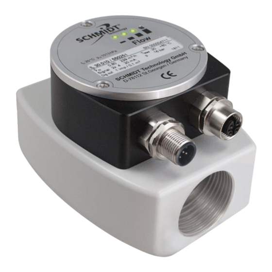
- Page 1 ® SCHMIDT Volume Flow Sensor IL 30.0xx Instructions for Use...
-
Page 2: Table Of Contents
Information concerning operation ..........13 Service information ................ 14 Technical data ................17 Dimensions ..................18 Declarations of Conformity ............19 Imprint: Copyright 2021 SCHMIDT Technology GmbH All rights reserved Version: 557006.02D Subject to modifications ® Instructions for Use - SCHMIDT Volume Flow Sensor IL 30.0xx... -
Page 3: Important Information
2). In particular, it is not designed for direct or indirect protec- tion of personal or machinery. SCHMIDT Technology cannot give any warranty as to its suitability for certain purpose and cannot be held liable for errors contained in these instructions for use or for accidental or sequential damage in connec- tion with the delivery, performance or use of this unit. -
Page 4: Application Range
Connection to the pipe system is carried out by the internal threads on both sides of the base body, suitable extended measuring sections are offered by SCHMIDT Technology as optional accessory (see Table 2). The IL 30.0xx measures both volume flow as well as the temperature of... -
Page 5: Mounting Instructions
The sensor probes can be damaged by ESD. To protect the sensitive inside, SCHMIDT Technology delivers the sensor with protective caps placed into both ends of its body which should be removed only before final installation. And vice versa when dismounting the sensor the protective caps should be attached in place immediately. - Page 6 The extended measuring sections, which are optionally available from SCHMIDT Technology (see subchapter Accessories), are delivered with two O-Rings which are intended as pressure seals for easy installation (must be applied by customer). If the customer uses his own pipes, suita- ble installation and sealing equipment must be used (e.g.
- Page 7 Accessories for installation ® For mounting of the SCHMIDT Volume Flow Sensor IL 30.0xx, there are several accessories available (see Table 2). Type / article No.
-
Page 8: Electrical Connection
View on connector of sensor (male) Table 3 Pin assignment The specified lead colours are valid for connecting cables from SCHMIDT Technology (see subchapter Accessories). During electrical installation ensure that no voltage is applied and inadvertent activation is not possible. - Page 9 (M12, female, A-coded, 5-pin) for connecting optional expan- sion modules (see Figure 1). Only expansion modules from SCHMIDT Technology may be connected to the module connector. Current of impulse output not included; operation current of IL 30.005 in brackets.
-
Page 10: Signalling
Medium temperature too high Table 4 LED off LED on: orange LED on: green LED flashes (1 Hz): rot „%“ of final value of measuring range of volume flow ® Instructions for Use - SCHMIDT Volume Flow Sensor IL 30.0xx Page 10... - Page 11 21.6 mA, see left image in Table 5). For higher values the output signal remains constant. Error signalling doesn’t take place because damage of the sensor is unlikely. In accordance to NAMUR specification ® Instructions for Use - SCHMIDT Volume Flow Sensor IL 30.0xx Page 11...
- Page 12 As long as the analogue flow volume output signals an error (2 mA), the pulse output is locked (high impedance). Switching hysteresis for the threshold is approx. 2 K. ® Instructions for Use - SCHMIDT Volume Flow Sensor IL 30.0xx Page 12...
-
Page 13: Commissioning
6 Commissioning ® Before applying supply voltage to the SCHMIDT Volume Flow Sensor IL 30.0xx the following checks have to be carried out: Mechanical mounting: o All screws are tightened properly. o Suitable pressure protection measures are carried out (e.g. sealing tape in the threads). -
Page 14: Service Information
For maximum accuracy in real applications, the SCHMIDT® Volume Flow Sensor IL 30.0xx MPM is matched in pressures > 3 bar. In order to avoid additional measurement deviations, the use of it at > 50 % of the measur- ing range is only recommended at pressures >... - Page 15 Load resistance of signal Connect load resistance to nently at maximum output is at +U Table 6 LED off LED on: orange LED on: green LED flashes (1 Hz): rot ® Instructions for Use - SCHMIDT Volume Flow Sensor IL 30.0xx Page 15...
- Page 16 Every new sensor is accompanied by a certificate of compliance according to EN 10204-2.1. Material certificates are not available. Upon request, we shall prepare, at a charge, a factory calibration certifi- cate, traceable to national standards. ® Instructions for Use - SCHMIDT Volume Flow Sensor IL 30.0xx Page 16...
-
Page 17: Technical Data
Based on standard (Norm) conditions T = 20 °C and p = 1013.25 hPa Minimal value of measuring range = lower detection limit fmr: final value of measuring range ® Instructions for Use - SCHMIDT Volume Flow Sensor IL 30.0xx Page 17... -
Page 18: Dimensions
Type Article number ges. IL 30.005 550 250 IL 30.010 MPM 550 251 IL 30.015 MPM 550 252 IL 30.020 MPM 550 253 All dimensions in mm ® Instructions for Use - SCHMIDT Volume Flow Sensor IL 30.0xx Page 18... -
Page 19: Declarations Of Conformity
11 Declarations of Conformity SCHMIDT Technology GmbH herewith declares in its sole responsibility, that the product SCHMIDT Volume Flow Sensor IL 30.0xx Part-Nos. 550 250, 550 251, 550 252, 550 253 is in compliance with the appropriate European guidelines and standards UK statutory requirements and designated standards. - Page 20 SCHMIDT Technology GmbH Feldbergstraße 1 78112 St. Georgen Germany Phone +49 (0)7724 / 899-0 +49 (0)7724 / 899-101 Email sensors@schmidttechnology.de www.schmidt-sensors.com www.schmidttechnology.de ® Instructions for Use - SCHMIDT Volume Flow Sensor IL 30.0xx Page 20...
Need help?
Do you have a question about the IL 30.0 Series and is the answer not in the manual?
Questions and answers