Table of Contents
Advertisement
Quick Links
Advertisement
Table of Contents

Subscribe to Our Youtube Channel
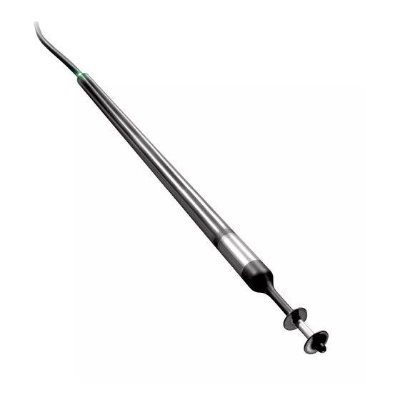
Summary of Contents for Schmidt SS 20.250
- Page 1 ® SCHMIDT Flow Sensor SS 20.250 Instructions for Use...
-
Page 2: Table Of Contents
® SCHMIDT Flow Sensor SS 20.250 Table of Contents Important Information ..............3 Application range ................4 Mounting instructions............... 4 Electrical connection..............10 Signalizations ................12 Startup ................... 14 Information concerning operation ..........14 Service information ................ 15 Technical data ................18 Declarations of conformity ............. -
Page 3: Important Information
2). In particular, it is not designed for direct or indirect protec- tion of personal or machinery. SCHMIDT Technology cannot give any warranty as to its suitability for certain purpose and cannot be held liable for accidental or sequen- tial damage in connection with the delivery, performance or use of this unit. -
Page 4: Application Range
3 Mounting instructions General information on handling The flow sensor SS 20.250 is a sensitive measuring instrument. There- fore, avoid applying mechanical force onto the sensor tip. The head of the sensor probe can be damaged irreversibly due to mechanical loads. - Page 5 Under the conditions mentioned above, a flattened, parabolic velocity pro- file is produced over the pipe cross-section which reaches its maximum Alternatively flow rectifiers, e.g. honeycomb ceramics, can be used. Instructions for Use – SCHMIDT ® Flow Sensor SS 20.250...
- Page 6 660.0 2,397 9,587 19,175 Table 2 SCHMIDT Technology provides a convenient calculation tool to compute flow velocity or volume flow in pipes (circular or rectangular) for all its sen- sor types and measuring ranges on its homepage. www.schmidt-sensors.com www.schmidttechnology.de Since the situation is similar to that in a pipe, the volumetric flow in a square chamber can be calculated in the same way, i.e.
- Page 7 Wall installation In general there are two options available for sensor installation on or (di- rectly) in a wall: Installation with a flange SCHMIDT Technology offers two types of flanges. 301048 Mounting flange 301048 Wall mounting flange 520181 Figure 3-4 The simple mounting flange (see Figure 3-4, left side) fixes the sensor by means of a locking screw and is not pressure-tight.
- Page 8 (mounting flange 301046) or lock nut (wall mounting flange 520181). Mounting with compression fitting SCHMIDT Technology offers two compression fittings that differ in mate- rial (brass or stainless steel; for details refer to subchapter Accessories). MID = 58.5...
- Page 9 Accessories ® The following accessories are available for mounting the SCHMIDT Flow Sensor SS 20.250. Type / art. no. Drawing Assembly Mounting flange - Immersion sensor - Wall (planar surface) 301048 - Attachement with: 3 screws (Ø < 5 mm)
-
Page 10: Electrical Connection
Voltage drops generated due to cable resistances must be considered by the customer. Both signal outputs 22 mA (maximum measuring values), minimum operating voltage. Instructions for Use – SCHMIDT ® Flow Sensor SS 20.250 Seite 10... - Page 11 Otherwise, AGND should be selected as measuring reference potential for the signal output. The signal outputs have a permanent short-circuit protection against both rails of the operating voltage. The maximum load capacity is 10 nF. Instructions for Use – SCHMIDT ® Flow Sensor SS 20.250 Seite 11...
-
Page 12: Signalizations
5 Signalizations Optical ® The SCHMIDT Flow Sensor SS 20.250 is equipped with a light ring on its cable exit that signals the current sensor state (refer to Table 5). Symbol Light Sensor state Supply voltage: none, wrong polarity, too low... - Page 13 Medium temperature below -20 °C The analog output for T switches to error (0 V or 2 mA). The analog output for w switches to error (0 V or 2 mA). Instructions for Use – SCHMIDT ® Flow Sensor SS 20.250 Seite 13...
-
Page 14: Startup
Even leaving the specified operating temperature range for a short period can cause an irreversible sensor damage. Environmental condition Medium The SS 20.250 is designed for the use in clean to slightly soiled media. Soiling or other gratings on the sensor cause distortions of measurements. -
Page 15: Service Information
The following table lists possible errors (error images) and a description to detect errors. Furthermore, possible causes and measures to be taken to eliminate errors are listed. Other cleaning fluids on request. Instructions for Use – SCHMIDT ® Flow Sensor SS 20.250 Seite 15... - Page 16 AGND B,DC Analog signal switches Measuring resistance of sig- Connect measuring re- between min. and max. nal output is at GND (U sistance to AGND B,AC Table 8 Instructions for Use – SCHMIDT ® Flow Sensor SS 20.250 Seite 16...
- Page 17 Every new sensor is accompanied by a certificate of compliance according to EN10204-2.1. Material certificates are not available. Upon request, we shall prepare, at a charge, a factory calibration certifi- cate, traceable to national standards. Instructions for Use – SCHMIDT ® Flow Sensor SS 20.250 Seite 17...
-
Page 18: Technical Data
Min. immersion depth 58 mm Probe length L 300 / 500 mm Weight 200 g max. (with 2 m cable) Under conditions of the reference. With cable end sleeves Instructions for Use – SCHMIDT ® Flow Sensor SS 20.250 Seite 18... -
Page 19: Declarations Of Conformity
10 Declarations of conformity SCHMIDT Technology GmbH herewith declares in its sole responsibility, that the product SCHMIDT Flow Sensor SS 20.250 Part-No. 526 340 is in compliance with the appropriate European guidelines and standards UK statutory requirements and designated standards. - Page 20 SCHMIDT Technology GmbH Feldbergstraße 1 78112 St. Georgen Germany Phone +49 (0)7724 / 899-0 +49 (0)7724 / 899-101 Email sensors@schmidttechnology.de www.schmidt-sensors.com www.schmidttechnology.de Instructions for Use – SCHMIDT ® Flow Sensor SS 20.250 Seite 20...


Need help?
Do you have a question about the SS 20.250 and is the answer not in the manual?
Questions and answers