Table of Contents
Advertisement
Quick Links
Advertisement
Table of Contents

Related Manuals for Custom Audio Electronics TPTCM60III


Summary of Contents for Custom Audio Electronics TPTCM60III
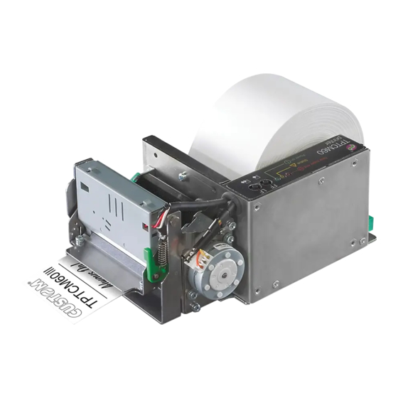
- Page 1 USER MANUAL TPTCM60III TPTCM60IIIL TPTCM112III TPTCM112IIIL...
- Page 3 CUSTOM S.p.A. GENERAL SAFETY INFORMATION THE CE MARK AFFIXED TO THE PRODUCT CERTIFY THAT THE Via Berettine 2/B Your attention is drawn to the following actions PRODUCT SATISFIES THE BA- that could compromise the characteristics of the 43010 Fontevivo (PARMA) - Italy SIC SAFETY REQUIREMENTS.
- Page 5 MANUAL For details on the commands, refer to the manual with code 77200000003100 For further information about the use of “PrinterSet” tool refer to the manual with code 78200000001800...
-
Page 7: Table Of Contents
TABLE OF CONTENTS 1 INTRODUCTION ............. 9 2 IDENTIFICATION OF THE MODELS . - Page 8 7 ALIGNMENT ..............79 7.1 Enable alignment .
-
Page 9: Introduction
1 INTRODUCTION This document is divided into sections and chapters. Each chapter can be reached by the index at the beginning of this document. The index can be reached by the button on each page as shown in the diagram below. Link to table of contents Notes reference Numbered title... -
Page 11: Identification Of The Models
2 IDENTIFICATION OF THE MODELS NOMENCLATURE DESCRIPTION TPTCM60III EJC TPTCM60III with ejector group and 200 dpi printhead TPTCM60III labels coniguration with 200 dpi printhead TPTCM60IIIL TPTCM112III base coniguration with 200 dpi printhead TPTCM112III TPTCM112III base coniguration with 300 dpi printhead TPTCM112III 300 DPI TPTCM112III STRONG CUT TPTCM112III with strong cut autocutter and 200 dpi printhead TPTCM112III EJC TPTCM112III with ejector group with 200 dpi printhead... -
Page 13: Description
Make sure that all the components illustrated below are present and that there are no signs of damage. If there are, contact customer service. TPTCM60III EJC 1. Installation instruction sheet 2. Device TPTCM60IIIL 1. - Page 14 TPTCM112III, TPTCM112III 300 DPI 1. Installation instruction sheet 2. Paper guide bracket with ixing screws (x 2) 3. Device TPTCM112III STRONG CUT, TPTCM112III CL 1. Installation instruction sheet 2. Paper guide brackets (internal and external) with ixing screws (x 4) 3. Device...
- Page 15 TPTCM112III EJC, TPTCM112III EJC 300 DPI 1. Installation instruction sheet 2. Device TPTCM112IIIL 1. Installation instruction sheet 2. Paper guide bracket with ixing screws (x 2) 3. Device...
-
Page 16: Device Components: External Views
3.2 Device components: external views TPTCM60III EJC 1. Printing mechanism + head temperature sensor 14. Low paper sensor 2. Sensor for paper presence in input 15. Roll holder pin 60 mm 3. LF LINE FEED key 16. External ring for roll blocking 4. - Page 17 TPTCM60IIIL 1. Printing mechanism + head temperature sensor 14. Connector for low paper sensor + cap (for optional adjust- 2. Paper out able paper roll) 3. Peeler 15. Low paper sensor 4. LF LINE FEED key 16. Roll holder pin 60 mm 5.
- Page 18 TPTCM112III, TPTCM112III 300 DPI, TPTCM112III CL 1. Printing mechanism lifting lever 14. Connector for low paper sensor + cap (for optional adjust- 2. Printing mechanism + head temperature sensor able paper roll) 3. Sensor for black mark alignment 15. Low paper sensor 4.
- Page 19 TPTCM112III STRONG CUT 1. Printing mechanism lifting lever 14. Connector for low paper sensor + cap (for optional adjust- 2. Printing mechanism + head temperature sensor able paper roll) 3. Sensor for black mark alignment 15. Low paper sensor 4. LF LINE FEED key 16.
- Page 20 TPTCM112III EJC, TPTCM112III EJC 300 DPI 1. Printing mechanism + head temperature sensor 14. Roll holder pin 112 mm 2. LF LINE FEED key 15. External ring for roll blocking 3. FF FORM FEED key 16. Cutter 4. POWER ON LED 17.
- Page 21 TPTCM112IIIL 1. Printing mechanism lifting lever 14. Power supply port 2. Printing mechanism + head temperature sensor 15. Connector for low paper sensor + cap (for optional adjust- 3. Upper sensor for labels gap detection able paper roll) 4. Lower sensor for labels gap detection 16.
-
Page 22: Product Label
3.3 Product label The main data used to identify the machine are shown on the label attached to the bottom of the device. In particular, it shows the electrical data for the connection to a power source. It also shows the product code, the serial number and the hardware revision (R). -
Page 23: Key Functions: Power Up
3.4 Key functions: power up POWER UP Hold down Hold down print perform the SETUP report FONT TEST Fast push Fast push Enter the skip the SETUP procedure SETUP PROCEDURE Fast push Fast push modify next selected parameter parameter... -
Page 24: Key Functions: Standby
3.5 Key functions: standby STANDBY Fast push Fast push Advance the paper Printing (preset length) demo ticket... -
Page 25: Status Messages
3.6 Status messages The three status LED indicate hardware status of device. Given in the table below are the various LEDs signals and the corresponding device status. POWER ON LED Signals the status of the powered device. STATUS LED DESCRIPTION DEVICE NOT POWERED GREEN DEVICE POWERED... - Page 26 STATUS LED Signals the hardware status of device. STATUS LED DESCRIPTION DEVICE OFF DEVICE ON: NO ERROR PRINTHEAD OVERHEATED PAPER END POWER SUPPLY VOLTAGE INCORRECT RECEPTION ERROR (PARITY, FRAME ERROR, OVERRUN ERROR) COMMAND NOT RECOGNIZED YELLOW COMMAND RECEPTION TIME OUT PRINTHEAD LIFTED PAPER JAM x 10...
-
Page 27: Installation
4 INSTALLATION 4.1 Fastening All the dimensions shown in following igures are in millimetres. TPTCM60III EJC The device is provided with three ixing holes on the bottom of device (see following igure). To install the device on a panel, use three M4 screws. 95 ± 0.1 54 ± 0.1 111.5 ± 0.3... - Page 28 TPTCM60IIIL The device is provided with three ixing holes on the bottom of device (see following igure). To install the device on a panel, use three M4 screws. Prepare the panel considering the presence of the rewinder and the paper path (see paragraph 5.4 paragraph 9.3). 95 ± 0.1 60.9 ± 0.3 27.5...
- Page 29 TPTCM112III, TPTCM112III EJC, TPTCM112III STRONG CUT, TPTCM112IIIL, TPTCM112III CL The device is provided with four ixing holes on the bottom of device (see following igure). To install the device on a panel, use four M4 screws. 74.5...
- Page 30 TPTCM112III EJC, TPTCM112III EJC 300 DPI The device is provided with four ixing holes on the bottom of device (see following igure). To install the device on a panel, use four M4 screws. 74.5...
-
Page 31: Connections
4.2 Connections The following igure shows the possible connections for the device. When the RS232 and USB communication cables are connected to the device at the same time, communication takes place via the USB port. Correctly insert the power supply connector with the flat side towards the device Serial Power supply standard cable standard cable cable (optional) Power supply serial device USB device... -
Page 32: Pinout
4.3 Pinout POWER SUPPLY Tripolar female connector 1 GND 2 +24 Vdc 3 GND 4 Frame GND The following igure shows the connector pinout of power supply cable: Tripolar male connector n.c. +24 V Power supply cable ATTENTION: Respect power supply polarity. USB INTERFACE Female USB type B connector 1 USB0_VBUS (out) 2 USB0_D- 3 USB0_D+... - Page 33 RS232 SERIAL INTERFACE Female DB9 connector 1 DT 2 TX During transmission, takes the values -VRS232 and + VRS232 depending on data 3 RX During reception, takes the values -VRS232 and +VRS232 depending on data 4 DS 5 GND 6 DT When +VRS232, device is power on 7 CT 8 RT...
- Page 34 LOW PAPER 4 ways male JST connector (S4B-PH-K-S) 1 VCC 2 QF-EXT (in) 3 QF-INT 4 GND The following igure shows the pinout of the connector of the cable for low paper to use for the device: Female JST connector Cable for low paper sensor series PHR-4 Cable Signal color Blue NPE (input) Black n.c. Yellow...
-
Page 35: Driver And Sdk
4.4 Driver and SDK The drivers for the following operating system are available in the website www.custom4u.it: OPERATING SYSTEM DESCRIPTION INSTALLATION PROCEDURE Driver for Windows XP Driver for Windows VISTA (32/64 bit) Driver for Windows 7 (32/64 bit) From the START menu, press Run and type-in the path where the SW Driver for Windows 8 (32/64 bit) Windows... -
Page 37: Operation
5 OPERATION 5.1 Adjusting paper width TPTCM60III EJC, TPTCM60IIIL The devices manage only 60 mm paper width roll. However, it is necessary to correctly place the two rings for roll blocking (internal and external) to ensure the right paper alignment inside the device. - Page 38 TPTCM112III, TPTCM112III 300 DPI, TPTCM112III EJC, TPTCM112III EJC 300 DPI, TPTCM112IIIL Paper width may be set to 80, 100 or 112 mm by assembling the internal adjustment ring and modifying the position of the external adjustment rings to ensure the right paper alignment inside the device (see the following igure). wing facing wing facing outwards outwards To manage paper width of 80, 86 or 100 mm, ix and correctly place the paper guide bracket provided with the device. The ...
- Page 39 TPTCM112III STRONG CUT, TPTCM112III CL Paper width may be set to 80, 86, 100 or 112 mm by modifying the position of the adjustment rings (internal and external) to ensure the right paper alignment inside the device (see the following igure). wing facing wing facing outwards outwards To manage paper width of 80, 86 or 100 mm, ix and correctly place the two paper guide brackets provided with the device. The following igure shows an example of bracket ixing for 86 mm paper width.
-
Page 40: Switch The Device On
(see (see paragraph 4.2) paragraph 4.2) Power supply cable (optional) TPTCM112III, TPTCM112III STRONG CUT, TPTCM60III EJC TPTCM112III EJC TPTCM60IIIL TPTCM112IIIL IN DC 24V 2.7A IN DC 24V 4.1A Connect the power supply cable to the device. Use the type of electrical power supply... -
Page 41: Loading The Paper Roll
5.3 Loading the paper roll To load the paper proceed as follows. At every change of paper, check inside the device to locate and remove any scraps of paper. TPTCM60III EJC, TPTCM60IIIL Insert the paper into the input mouth. Assemble the two rings Assemble the two rings as described in the previous paragraphs. - Page 42 TPTCM112III, TPTCM112III 300 DPI, TPTCM112III STRONG CUT, TPTCM112III EJC, TPTCM112III EJC 300 DPI, TPTCM112IIIL, TPTCM112III CL Insert the paper into the input mouth. Be sure that the paper is correctly positioned into paper guides. If necessary, adjust the paper width by assembling If necessary, adjust the paper width by assembling the two rings and the paper guides (see paragraph...
-
Page 43: Fixing The Paper On Rewinder
5.4 Fixing the paper on rewinder TPTCM60IIIL Insert the paper into the device (see paragraph 5.3). Load the paper into the device as described in the previous paragraphs. ± 200 mm Press the LF LINE FEED button repeatedly to advance the paper of at least 200 mm beyond the edge of the peeler. - Page 44 Remove all labels on the media, beyond the paper mouth. Paper Metal pin Pull the paper toward the rewinder respecting the path indicated by the arrows.
- Page 45 Remove the rewinder plastic disk and wrap the paper around the pin as indicated by the arrow. Block the paper by inserting the plastic disk.
-
Page 46: Issuing Ticket
5.5 Issuing ticket The device allows you to choose between diferent operating modes for the issuance of printed tickets. The operating modes shown in the following images, depend on the settings of the coniguration parameters and com- mands sent to the device. “PRINT” mode - TPTCM112III, TPTCM112III 300 DPI, TPTCM112III STRONG CUT, TPTCM112IIIL, TPTCM112III CL Paper input Printhead The device starts the ticket printing. Autocutter Paper output Ticket issued When printing ends, the device cuts the ticket printed that is issued from the paper output. - Page 47 “EJECT” mode (continuous mode disabled) - TPTCM60III EJC, TPTCM112III EJC, TPTCM112III EJC 300 DPI Paper input Printhead The device starts the ticket printing. Ejector rollers Printhead The ticket advances ahead to the ejector and is caught between the ejector rollers.
- Page 48 Autocutter Ejector rollers When printing ends, the device cuts the ticket printed Ejector rollers Paper output Ticket issued The device directly ejects the ticket NOTE: To enable this issuing mode, you need to correctly set the operation mode of the ejector with the command 0x1D 0x65 (see commands manual).
- Page 49 “EJECT” mode (continuous mode enabled) - TPTCM60III EJC, TPTCM112III EJC, TPTCM112III EJC 300 DPI Paper input Printhead The device starts the ticket printing. Ejector rollers Paper output The ticket goes beyond the ejector rollers and starts to come out of the paper output.
- Page 50 Autocutter Paper output When printing ends, the device cuts the ticket printed. Ejector rollers Paper output Ticket issued The device ejects the ticket. NOTE: To enable this issuing mode, you need to correctly set the operation mode of the ejector with the command 0x1D 0x65 (see commands manual).
- Page 51 “PRESENT” mode (continuous mode disabled) - TPTCM60III EJC, TPTCM112III EJC, TPTCM112III EJC 300 DPI Paper input Printhead The device starts the ticket printing. Printhead Ejector rollers The ticket advances ahead to the ejector and is caught between the ejector rollers.
- Page 52 Autocutter Ejector rollers When printing ends, the device cuts the ticket printed. Ejector rollers Paper output Ticket presented The device presents the ticket printed on the paper output.
- Page 53 Paper output Ticket withdrew The user withdraws the ticket from the paper output. NOTE: To enable this issuing mode, you need to correctly set the operation mode of the ejector with the command 0x1D 0x65 (see commands manual) and the setup parameter "Automatic Ejecting" (see chapter...
- Page 54 “PRESENT” mode (continuous mode enabled) - TPTCM60III EJC, TPTCM112III EJC, TPTCM112III EJC 300 DPI Paper input Printhead The device starts the ticket printing. Ejector rollers Paper output The ticket goes beyond the ejector rollers and stanrts to come out of the paper output...
- Page 55 Autocutter Paper output When printing ends, the device cuts the ticket printed. Ejector rollers Paper output Ticket presented The device presents the ticket printed on the paper output.
- Page 56 Paper output Ticket withdrew The user withdraws the ticket from the paper output. NOTE: To enable this issuing mode, you need to correctly set the operation mode of the ejector with the command 0x1D 0x65 (see commands manual) and the setup parameter "Automatic Ejecting" (see chapter...
- Page 57 “PRESENT” mode - TPTCM60IIIL Paper input Printhead The device performs the label printing. Label presented When printing ends, the device presents the label printed on the output peeler.
- Page 58 Withdrawn label The user withdraws the printed label.
- Page 59 “PRESENT/EJECT” mode (continuous mode disabled) - TPTCM60III EJC, TPTCM112III EJC, TPTCM112III EJC 300 DPI Paper input Printhead The device starts the ticket printing. Printhead Ejector rollers The ticket advances ahead to the ejector and is caught between the ejector rollers.
- Page 60 Autocutter Ejector rollers When printing ends, the device cuts the ticket printed. Ejector rollers Paper output Ticket presented The device presents the ticket printed on the paper output.
- Page 61 The ticket is waiting on the paper mouth for a preset period of time. Ejector rollers Paper output Ticket issued The device ejects the ticket. NOTE: To enable this issuing mode, you need to correctly set the operation mode of the ejector with the command 0x1D 0x65 (see commands manual) and the setup parameter "Automatic Ejecting"...
- Page 62 “PRESENT/EJECT” mode (continuous mode enabled) - TPTCM60III EJC, TPTCM112III EJC, TPTCM112III EJC 300 DPI Paper input Printhead The device starts the ticket printing. Ejector rollers Paper output The ticket goes beyond the ejector rollers and stanrts to come out of the paper output.
- Page 63 Autocutter Paper output When printing ends, the device cuts the ticket printed. Ejector rollers Paper output Ticket presented The device presents the ticket printed on the paper output.
- Page 64 The ticket is waiting on the paper mouth for a preset period of time. Ejector rollers Paper output Ticket issued The device ejects the ticket. NOTE: To enable this issuing mode, you need to correctly set the operation mode of the ejector with the command 0x1D 0x65 (see commands manual) and the setup parameter "Automatic Ejecting"...
-
Page 65: Configuration
6 CONFIGURATION 6.1 Coniguration by keys To enter the coniguration mode and print a setup report with the operating parameters of the device, proceed as follows. LF LINE FEED Correctly insert the power supply connector with the flat side towards the device While pressing the LF LINE FEED key, switch on the device by connecting the power supply cable. PRINTER SETUP The device prints the report with the settings parameters. - Page 66 The following igure shows the setup report of the device. The shown values for parameters are sample values; for the list and the description of device parameters see the following paragraphs. DEVICE NAME AND <device name> FIRMWARE MODULES SCODE. <code> rel 1.00 DCODE. <code> rel 1.00 RELEASE FCODE. <code> rel 1.00 PRINTER SETTINGS PRINTER TYPE ........<device model> PRINTING HEAD TYPE ......<head model> INTERFACE ..........USB PROGRAM MEMORY TEST....OK DYNAMIC RAM TEST......OK...
-
Page 67: Coniguration By Software
6.2 Coniguration by software The setup parameters can be set by using the “PrinterSet” software tool available on www.custom4u.it. For a detailed description of the device operating parameters see the following paragraphs. To conigure the device by software, proceed as follows: Connect the device to a PC directly (see paragraph 4.2), Connect the device to a PC directly (see paragraph 4.5),... - Page 68 LOAD SAVE PORT SETUP FONTS UPGRADE H. reflect V. reflect Click on SETUP to access the operating parameteres of the device to be configured. PORT LOAD SAVE EXTRA SETUP Description <Parameter> Disabled Activation of the Bluetooth® module <Parameter> Enabled or WiFi on the device. If the “Wireless” parameter is set to ON (active) do not <Parameter>...
-
Page 69: Coniguration By Ile
6.3 Coniguration by ile The setup parameters can be set by editing the “Setup.ini” ile stored on the Flash Drive of the device. Proceed as follows: Enter setup Enter the coniguration procedure Enter the configuration procedure by keys (see paragraph 6.1) by keys (see paragraph 6.1) or by software (see paragraph 6.2). or by software (see paragraph 6.2). Plug the device to a Personal Computer via USB. - Page 70 The “Setup.ini” ile is a coniguration ile that contains all the conigurable parameters listed in text format and divided into some sections (indicated between square brackets). For each parameter, you ind the parameter name followed by the value currently set and then the available values listed with a reference number. The reference number marked with the symbol ‘ * ’ is the default one (see igure). Value set Section [PRINT] Parameter name Speed / Quality = 2 0 = High Quality 1 = Normal // * 2 = High Speed Availables values Default marker...
-
Page 71: Device Status
6.4 Device status The device operating status is indicated in the coniguration print-out in which, next to the name of the components dis- played, the following information is given. device model PRINTER TYPE PRINTING HEAD TYPE printing head model INTERFACE interface present PROGRAM MEMORY TEST OK appears if functioning and NOT OK if faulty DYNAMIC RAM TEST OK appears if functioning and NOT OK if faulty OK appears if functioning and NOT OK if faulty EXTERNAL MEMORY TEST CUTTER TEST... -
Page 72: Communication Parameters
6.5 Communication parameters The device allows the coniguration of the parameters listed in the following table. The parameters marked with the symbol are the default values. Settings remain active even after the device has been turned of and they are stored in non-volatile memory. Communication speed of the serial interface: RS232 BAUD RATE 9600 57600 19200 115200 38400 Parameter valid only with serial interface. RS232 DATA LENGTH Number of bit used for characters encoding: 7 bits/car 8 bits/car Parameter valid only with serial interface. -
Page 73: Operating Parameters
6.6 Operating parameters This device allows the coniguration of the parameters listed in the following table. The parameters marked with the symbol are the default values. Settings remain active even after the device has been turned of and they are stored in non-volatile memory. Available emulations for the device: PRINTER EMULATION CUSTOM/POS TPTCMII CUSTOM TPT PRINT MODE Printing mode: Normal = enables printing in normal writing way Reverse = enables printing rotated 180 degrees AUTOFEED Setting of the Carriage Return character: CR disabled... - Page 74 Enabled T.out 60s = the ticket is ejected after 60 seconds from the end of printing Enabled T.out 2m = the ticket is ejected after 2 minutes from the end of printing This parameter is printed only with TPTCM60III EJC, TPTCM112III EJC and TPTCM112III EJC 300 DPI.
- Page 75 PANEL KEY Panel key management: Disabled = Panel key disabled. Enabled = Panel key enabled. PAPER THRESHOLD Threshold value (in percent) for the recognition of paper presence by the paper presence sensor: Cleaning mode of data in receive bufer, if the printing is stopped due to lack of paper: PAPEREND BUFFER CLEAR = Data remain in the receive bufer. When the paper runs out, the device keeps Disabled the remaining data in receive bufer and prints the remaining portion of ticket after that the new paper is loaded.
-
Page 76: Alignment Parameters
6.7 Alignment parameters The device allows the coniguration of the parameters listed in the following table. The parameters marked with the symbol are the default values. Settings remain active even after the device has been turned of and they are stored in non-volatile memory. BLACK MARK POSITION Black mark or gap alignment management: Disabled alignment is not performed Enabled = alignment is performed BLACK MARK THRESHOLD Threshold value (in percent) for the recognition of the presence of notch by the notch sensor: For TPTCM112III CL the default value is 40%. -
Page 77: Hexadecimal Dump
6.8 Hexadecimal dump This function is used for the diagnosis of the characters received from the communications port. Characters are printed as hexadecimal code and the corresponding ASCII code (see below). Each line is preceded by a counter in hexadecimal that indicates the number of bytes received. -
Page 79: Alignment
7 ALIGNMENT Devices are provided with sensors for the alignment management in order to handle: rolls of tickets with pre-printed ields and a ixed length; • rolls of labels with a ixed length. • The alignment notch may be formed by • black mark printed on paper (see paragraph 9.7); • gap between two labels (see paragraph 9.7);... -
Page 80: Enable Alignment
7.1 Enable alignment TPTCM60IIIL Device is provided with a fork sensors for alignment, placed on the right side of the paper input mouth: RIGHT FORK SENSOR To guarantee the correct alignment, you must enable the parameter “Black Mark Position” during the setup procedure (see chapter If the alignment does not work properly, perform the labels gap detection sensor autoset procedure (see paragraph... - Page 81 The following igure shows an example of paper with label usable with the device: RIGHT FORK SENSOR direction LABELS paper feed ROLL...
- Page 82 TPTCM112III, TPTCM112III STRONG CUT, TPTCM112III CL The device is equipped with an alignment sensor that can be positioned in three diferent positions. In standard coniguration, the sensor is positioned in position A. SENSOR IN POSITION A SENSOR IN SENSOR IN POSITION B POSITION C...
- Page 83 To place the sensor in positions B or C, proceed as follows. Unscrew the fixing screw A and remove the washer B. Move the lower paper guide away C being careful not to damage the cables. Unscrew the fixing screw D and remove the alignment sensor E.
- Page 84 SENSOR IN POSITION B To position the sensor in position B, rotate the sensor 180 ° and fix it in the previous position with the previously removed fixing screw. Make sure to match the pin of the paper guide with the hole in the alignment sensor board. SENSOR IN POSITION C To position the sensor in position C, rotate the sensor 180 °...
- Page 85 Reposition the lower paper guide C in its seat and fix it with the fixing screw A and the washer B.
- Page 86 The following igure shows an example of paper with black mark usable with the device: NON-THERMAL SIDE SENSOR IN POSITION C direction paper feed SENSOR IN SENSOR IN PAPER POSITION A POSITION B ROLL To guarantee the correct alignment, you must enable the parameter “Black Mark Position” during the setup procedure (see chapter...
- Page 87 TPTCM112IIIL Device is provided with two sensor for alignment, placed as follows: a ixed sensor placed on the center, at the bottom of input paper mouth, • a ixed sensor placed on the center, at the top of input paper mouth • CENTRAL CENTRAL LOWER SENSOR UPPER SENSOR To guarantee the correct alignment, you must enable the parameter “Black Mark Position” during the setup procedure (see chapter If the alignment does not work properly, perform the labels gap detection sensor autoset procedure (see paragraph...
- Page 88 The following igure shows an example of paper with black mark usable with the device: CENTRAL UPPER SENSOR direction CENTRAL LABELS paper feed LOWER SENSOR ROLL...
-
Page 89: Calibration
7.2 Calibration The sensor calibration occurs automatically and consists in adjusting the quantity of light emitted to match the degree of whiteness of the paper used and the degree of black of the mark printed on paper. The device automatically performs the self-calibration during the setup procedure only if the “Black Mark Position” parameter is set to a value other than “Disabled”... - Page 90 The following igure shows an example of paper with the non-thermal paper printed with black marks and other graphics (for example, a barcode): the outgoing voltage is constant while passing the white paper between two notches, presents a peak at each black mark and presents some “noise” at each barcode. In this case, the optimal value for the “Black Mark Threshold”...
-
Page 91: Labels Gap Detection Sensor Autoset Procedure
7.3 Labels gap detection sensor autoset procedure TPTCM60IIIL, TPTCM112IIIL Disconnect the power supply cable. Open the printhead by rotating the printhead lifting lever. Remove all labels on the support near the paper inlet and bezel. There should be no labels under the printing mechanism. - Page 92 Close the printhead by rotating the printhead lifting lever. Connect the power supply cable to the device. Connect the device to a PC directly (see paragraph 4.2), Connect the device to a PC directly (see paragraph 3.1), without using HUB devices. without using HUB devices.
- Page 93 Start the “PrinterSet” software tool. LOAD SAVE PORT From Device From File Select a configuration file as follows: Click on LOAD > FROM DEVICE and select the device connected to the PC. Click on LOAD > From file and select a .psc file on your PC Drag and drop a .psc file Click on TOOLS.
- Page 94 Click on BLACKMARK AUTOTEST. Attendere il completamento della procedura di autoset da parte del dispositivo.
-
Page 95: Alignment Parameters
7.4 Alignment parameters TPTCM60IIIL, TPTCM112IIIL When you use paper with label, the “alignment point” is always meant as the label edge and match with the rear front of the gap between two labels. The gap width is automatically detected and measured by the sensors of the device. Alignment point: rear front of the gap PRINTING DIRECTION... - Page 96 TPTCM60IIIL A = distance between printhead and alignment sensor = 36.5 mm B = distance between printhead and peeler output = 47 mm To enable the alignment management you need to enable the “Black Mark Position” as described in chapter...
- Page 97 TPTCM112III, TPTCM112III STRONG CUT, TPTCM112III CL The “alignment point” is deined as the position inside the ticket to use for the notch alignment. The distance between the notch edge and the alignment point is deined as “Black Mark Distance”. Referring to the front of the notch, the value of “Black Mark Distance” value varies from 0 mm minimum and 99.9 mm maximum. If the “Black Mark Distance” value is set to 0, the alignment point is set at the beginning of the notch. Alignment Alignment point:...
- Page 98 To deine the alignment point you need to set the printer parameters that compose the numerical value of the “Black Mark Distance” parameter. (see paragraph 6.7). For example, to set a black mark distance of 15 mm between the black mark and the alignment point, the parameters must be set on the following values: Black Mark Distance Sign Black Mark Distance [mm x 10] Black Mark Distance [mm x 1] Black Mark Distance [mm x .1] The “Black Mark Distance” parameter, may be modiied as described in chapter...
-
Page 99: Printing Area
7.5 Printing area TPTCM60IIIL, TPTCM112IIIL In order to issue labels correctly printed and to not overlay printing to the next label (that will make it useless for the next alignment), it is important to well calibrate the length of the printing area according to the label length. The following igure shows an example of printed labels: Printing line Printing line... - Page 100 TPTCM112III, TPTCM112III STRONG CUT, TPTCM112III CL In order to print ticket containing only one notch and to not overlay printing to a notch (that will make it useless for the next alignment), it is important to well calibrate the length of the printing area of ticket according to the inter-notch distance. The following igure shows an example of tickets with “Black Mark Distance” set to 0: Cutting line Printing line...
-
Page 101: Maintenance
8 MAINTENANCE 8.1 Paper jam TPTCM60III EJC, TPTCM112III EJC, TPTCM112III EJC 300 DPI Unlock the ejector group by using the lever. Lift and keep open the ejector cover. Remove the damaged paper and check the presence Lift the ejector group for paper scraps inside the ejector. - Page 102 Be careful not to damage the connection cable for the printing mechanism Remove the damaged paper Remove the damaged paper if present on the cutter input. if present under the printing mechanism. Unlock the printing mechanism as shown in figure.
- Page 103 TPTCM112III, TPTCM112III 300 DPI, TPTCM112III STRONG CUT, TPTCM112IIIL, TPTCM112III CL Be careful not to damage the connection cable for the cutter group Unlock the printing mechanism as shown in figure. Be careful not to damage the connection cable for the printing mechanism Unscrew the two fixing screws and remove the cutter group.
-
Page 104: Planning Of Cleaning Operations
NOTES: For some models is represented only the internal printer group. (1) Only for TPTCM60III EJC, TPTCM112III, TPTCM112III 300 DPI, TPTCM112III STRONG CUT, TPTCM112III EJC, TPTCM112III EJC 300 DPI and TPTCM112IIIL. (2) Only for TPTCM60III EJC, TPTCM112III EJC and TPTCM112III EJC 300 DPI. -
Page 105: Cleaning
8.3 Cleaning For periodic cleaning of the device, see the instructions below. Printhead - TPTCM60III EJC, TPTCM112III EJC, TPTCM112III EJC 300 DPI Disconnect the power supply cable and Disconnect the power supply cable and lift the ejector group (see paragraph 8.1). - Page 106 Printhead - TPTCM112III, TPTCM112III 300 DPI, TPTCM112III STRONG CUT, TPTCM112IIIL Disconnect the power supply cable. Unlock the printing mechanism as shown in figure. Be careful not to damage the connection cable for the autocutter group ISOPROPYL ALCOHOL ATTENTION: Do not use solvents, or hard brushes. Do not let water or other liquids get inside the machine.
- Page 107 Printhead - TPTCM60IIIL Disconnect the power supply cable. ISOPROPYL ALCOHOL ATTENTION: Do not use solvents, or hard brushes. Do not let water or other liquids get inside the machine. Clean the printhead by using a non-abrasive cloth moistened with isopropyl. Unlock the printing mechanism as shown in figure.
- Page 108 Platen roller Disconnect the power supply cable. ISOPROPYL ALCOHOL ATTENTION: Do not use solvents, or hard brushes. Do not let water or other liquids get inside the machine. Clean the platen roller by using a non-abrasive cloth moistened with isopropyl alcohol. Unlock the printing mechanism by following the specific procedure for each model as described in the previous paragraphs.
- Page 109 Sensor for paper presence in input Disconnect the power supply cable. ATTENTION: Do not use alcohol, solvents, or hard brushes. Do not let water or other liquids get inside the device. Alcohol, solvent Clean the paper presence sensor in input by using compressed air.
- Page 110 Ejector (TPTCM60III EJC, TPTCM112III EJC, TPTCM112III EJC 300 DPI) Disconnect the power supply cable. ISOPROPYL ALCOHOL ATTENTION: Do not use solvents, or hard brushes. Do not let water or other liquids get inside the machine. Lift and keep open the ejector cover.
- Page 111 Autocutter (TPTCM112III, TPTCM112III 300 DPI, TPTCM112III STRONG CUT, TPTCM112IIIL) Disconnect the power supply cable. Unlock the autocutter group by using the lever. ATTENTION: Do not use alcohol, solvents, or hard brushes. Do not let water or other liquids get inside the device. Alcohol, solvent Remove any scraps of paper and the accumulated paper dust on the autocutter input...
- Page 112 Autocutter (TPTCM60III EJC, TPTCM112III EJC) Case Disconnect the power supply cable and Disconnect the power supply cable and lift the ejector group (see paragraph 8.1). lift the ejector group (see previous paragraphs). Disconnect the power supply cable. ATTENTION: Do not use alcohol, solvents, or hard brushes.
-
Page 113: Firmware Upgrade
8.4 Firmware upgrade Firmware upgrade can be performed by using the “PrinterSet” software tool available on www.custom4u.it. To upgrade irmware, proceed as follows: Login to the website www.custom4u.it, type in the product code of the device Login to the website www.custom4u.it, type in the product code of the device and download the latest irmware release available. - Page 114 LOAD SAVE PORT EXTRA HELP From Device From File Select a con guration le as follows: Click on LOAD > From device and select a device connected with the PC Click on LOAD > From file and select a .psc file on your PC Drag and drop a .psc file Click on LOAD >...
-
Page 115: Specification
9 SPECIFICATION 9.1 Hardware speciications GENERAL Sensors TPTCM60III EJC Head temperature, paper presence in input, print head lifted, TPTCM112III EJC low paper, paper presence on output, ejector position TPTCM112III EJC 300 DPI Head temperature, paper presence in input, print head lifted,... - Page 116 PRINTER Resolution TPTCM60III EJC TPTCM60IIIL TPTCM112III TPTCM112III STRONG CUT 203 dpi (8 dot/mm) TPTCM112III EJC TPTCM112IIIL TPTCM112III CL TPTCM112III 300 DPI 304 dpi (12 dot/mm) TPTCM112III EJC 300 DPI Thermal, ixed head Printing method Head life Abrasion resistance 100 km (with recommended paper, 12.5% duty cycle)
- Page 117 PAPER Type of paper Thermal rolls, heat-sensitive side on outside of roll Paper width TPTCM60III EJC 60 mm ± 0.5 mm TPTCM60IIIL TPTCM112III TPTCM112III STRONG CUT 80 mm ± 0.5 mm TPTCM112III 300 DPI 86 mm ± 0.5 mm TPTCM112III EJC 100 mm ±...
- Page 118 0.055 mm Liner trasparency Trasparency 47% Liner total thickness 0.15 mm ± 10% AUTOCUTTER (TPTCM60III EJC, TPTCM112III, TPTCM112III 300 DPI, TPTCM112III STRONG CUT, TPTCM112III EJC, TPTCM112III EJC 300 DPI, TPTCM112IIIL, TPTCM112III CL) Paper cut Total cut Estimated life 1000000 cuts (with paper thickness 100 μm, ambient temperature) TPTCM60III EJC...
- Page 119 TPTCM112III EJC 300 DPI TPTCM112IIIL TPTCM112III CL Standby consumption 50 mA POWER SUPPLY ELECTRICAL SPECIFICATIONS code 963GE020000071 (optional for TPTCM60III EJC and TPTCM60IIIL) Power supply voltage from 90 Vac to 264 Vac Frequency from 47 Hz to 63 Hz Output 24 V, 2.5 A...
- Page 120 (5) : Referred to the UL measurements (Speed/Quality = Normal, Ticket = 100 mm, Print Density = 50%, 50% dots on, 1 ticket every 30 s). (6) : If you use TPTCM60III EJC or TPTCM60IIIL with the power supply code 963GE020000071, supplied as an ac- cessory, the operating temperature range is from 0 °C to +40 °C.
-
Page 121: Character Speciications
9.2 Character speciications TPTCM60III EJC, TPTCM60IIIL Character set Character density 11 cpi 15 cpi 20 cpi Number of columns Chars / second 1213 1680 2240 Lines / second Characters (L x H mm)-Normal 2.25 x 3 1.625 x 3 1.25 x 3... -
Page 122: Device Dimensions
9.3 Device dimensions TPTCM60III EJC Length 265.5 mm Height 80.3 mm Width 115 mm Weight 1500 g All the dimensions shown in following igure are in millimetres. 105.5 95 ± 0.1 54 ± 0.1 111.5 ± 0.3 paper width 89.5 129.5 214.42 237.5 249.5 Ø23... - Page 123 TPTCM60IIIL Length 188.4 mm Height 195.3 mm Width 112.4 mm Weight 1150 g All the dimensions shown in following igure are in millimetres. 95 ± 0.1 60.9 ± 0.3 160.9 148.9 40.9 27.5 62.2 122.9 Ø23...
- Page 124 TPTCM112III, TPTCM112III 300 DPI, TPTCM112III CL Length 227.4 mm (with autocutter down) 95.3 mm Height (with autocutter up) 136.6 mm Width 171.55 mm Weight 1700 g All the dimensions shown in following igure are in millimetres. 60.5 74.5 136.55 95.3 92.3 ±1 69.5 50.1 ±1 46.1 ±1 23.8 ±1 91.55 57.5 Ø18...
- Page 125 TPTCM112III STRONG CUT Length 227.4 mm (with autocutter down) 95.3 mm Height (with autocutter up) 138.6 mm Width 171.55 mm Weight 1700 g All the dimensions shown in following igure are in millimetres. 60.5 74.5 138.6 95.3 93.6 ±1 69.5 50.1 ±1 46.1 ±1 23.8 ±1 91.5 71.9 57.5 Ø18 57.5...
- Page 126 TPTCM112III EJC, TPTCM112III EJC 300 DPI Length 300 mm (with ejector down) 95.3 mm Height (with ejector up) 223.1 mm Width 171.55 mm Weight 2100 g All the dimensions shown in following igure are in millimetres. 60.5 74.5 223.1 95.3 92.3 ±1 69.5 66.3 ±1 47 ±1 25.3 ±1 91.55 82.2 Ø18...
- Page 127 TPTCM112IIIL Length 227.4 mm (with autocutter down) 95.3 mm Height (with autocutter up) 136.6 mm Width 171.55 mm Weight 1700 g All the dimensions shown in following igure are in millimetres. 60.5 74.5 136.6 95.3 92.3 ±1 69.5 50.1 ±1 46.1 ±1 23.8 ±1 91.55 57.5 Ø18 57.5...
-
Page 128: Device Dimensions With Paper Roll Holder
9.4 Device dimensions with paper roll holder code 974EX010000316 (optional) TPTCM60III EJC max. 352.5 mm Length max. 397.5 mm (with paper roll Ø max.160 mm) max. 183.7 mm Height max. 228.7 mm (with paper roll Ø max.160 mm) Width 115 mm All the dimensions shown in following igure are in millimetres. - Page 129 TPTCM60IIIL Length max. 275.4 mm Height max. 298.7 mm Width 112.4 mm All the dimensions shown in following igure are in millimetres. 137.1 45° 40.9 27.5 122.9...
-
Page 130: Device Dimensions With Paper Roll Holder
9.5 Device dimensions with paper roll holder code 974EU010000315 (optional) TPTCM112III, TPTCM112III 300 DPI, TPTCM112III STRONG CUT, TPTCM112IIIL, TPTCM112III CL max. 325.4 mm Length max. 370.4 mm (with paper roll Ø max.160 mm) max. 223.4 mm Height max. 268.4 mm (with paper roll Ø max.160 mm) Width 115 mm All the dimensions shown in following igure are in millimetres. - Page 131 TPTCM112III EJC, TPTCM112III EJC 300 DPI max. 398 mm Length max. 443 mm (with paper roll Ø max.160 mm) max. 223.4 mm Height max. 268.4 mm (with paper roll Ø max.160 mm) Width 115 mm All the dimensions shown in following igure are in millimetres. 92.3 ±1 66.3 ±1 47 ±1 25.3 ±1...
-
Page 132: Power Supply And Power Cord Dimensions
The following table shows the dimensions of the power supply, the power cord and the adapter for power supply optionals for the device. POWER CORD code 26100000000311 (optional for TPTCM60III EJC and TPTCM60IIIL) Length 2000 mm POWER SUPPLY code 963GE020000071... - Page 133 POWER SUPPLY code 963GE020000071 AC INLET DC OUTPUT WIRE 30 ± 5 130 ± 1 1500 n.c. +24V POWER SUPPLY code 963GE020000106 AC INLET 1500 ± 30 30 ± 5 DC OUTPUT WIRE 146.2 ± 0.5 +24V...
-
Page 134: Paper Speciication
9.7 Paper speciication TPTCM60IIIL, TPTCM112IIIL To properly use the alignment commands, you need to use paper with labels that comply with the dimensions shown in the following igure that apply to all paper widths handled by the devices. All the dimensions shown in following igures are in millimetres. < 6 mm < 6 mm PAPER WIDTH... - Page 135 TPTCM112III, TPTCM112III 300 DPI, TPTCM112III STRONG CUT, TPTCM112III CL The following image shows the placement of the black mark on paper. The notch must be printed on the non-thermal side of paper according to the dimensions shown in the following igure that apply to all paper widths handled by the device. For devices with the alignment sensor in position C (see chapter 7), the paper speciications are symmetric to the axis of ...
-
Page 136: Character Sets
9.8 Character sets The device has 3 fonts of varying width (11, 15 and 20 cpi) which may be related one of the coding tables provided on the device. To know the coding tables actually present on the device, you need to print the font test (see paragraph 3.4). - Page 137 <CodeTable> Coding table PC720 - Arabic on request WPC775 - Baltic Rim on request PC855 - Cyrillic on request PC861 - Icelandic on request PC862 - Hebrew PC864 - Arabic PC869 - Greek on request ISO8859-2 - Latin 2 on request ISO8859-15 - Latin 9 on request PC1098 - Farsi...
-
Page 139: Consumables
10 CONSUMABLES The following table shows the list of available consumables for devices: TPTCM60III EJC, TPTCM60IIIL 67300000000370 THERMAL PAPER ROLL weight = 74 g/m width = 60 mm Ø external = 95 mm Ø core = 25 mm 67300000000352 THERMAL PAPER ROLL... -
Page 141: Accessories
11 ACCESSORIES The following tables shows the list of available accessories for device. TPTCM60III EJC, TPTCM60IIIL 963GE020000071 POWER SUPPLY (for technical speciications, see paragraph 9.1) 26100000000311 POWER CORD SCHUKO PLUG length = 2 m (see paragraph 9.6) 26600000000012 ADAPTER CABLE 3 pin male power-DIN connector... - Page 142 21100000001349 TIE FOR ROLL LOCKING 21400000000948 PLASTIC BEZEL...
- Page 143 TPTCM112III, TPTCM112III 300 DPI, TPTCM112III STRONG CUT, TPTCM112III EJC, TPTCM112III EJC 300 DPI, TPTCM112IIIL, TPTCM112III CL 963GE020000106 POWER SUPPLY (for technical speciications, see paragraph 9.1) 26600000000012 ADAPTER CABLE 3 pin male power-DIN connector length = 50 cm 26300000000603 LOW PAPER SENSOR BOARD with cable length = 200 mm 974EU010000315 ADJUSTABLE PAPER ROLL HOLDER with low paper sensor board and cable...
-
Page 145: Technical Service
12 TECHNICAL SERVICE In case of failure, contact the technical service accessing the website www.custom4u.it and using the support tools on the homepage. It is advisable to keep the identiication data of the product at hand. The product code, the serial number and the hardware release number can be found on the product label (see paragraph 3.3). - Page 148 CUSTOM S.p.A. World Headquarters Via Berettine, 2/B - 43010 Fontevivo, Parma ITALY Tel. +39 0521 680111 - Fax +39 0521 610701 info@custom.biz - www.custom.biz All rights reserved www.custom.biz...
Need help?
Do you have a question about the TPTCM60III and is the answer not in the manual?
Questions and answers