Table of Contents
Advertisement
Advertisement
Table of Contents

Related Manuals for Custom Audio Electronics TG2480HIII


Summary of Contents for Custom Audio Electronics TG2480HIII
- Page 1 USER MANUAL TG2480HIII...
- Page 3 CUSTOM S.p.A. GENERAL SAFETY INFORMATION THE CE MARK AFFIXED TO THE PRODUCT CERTIFY THAT THE Via Berettine 2/B Your attention is drawn to the following actions PRODUCT SATISFIES THE BA- that could compromise the characteristics of the 43010 Fontevivo (PARMA) - Italy SIC SAFETY REQUIREMENTS.
- Page 5 MANUAL For details on the commands, refer to the manual with code 77200000005200 For further information about the use of “PrinterSet” tool refer to the manual with code 78200000001800...
-
Page 7: Table Of Contents
TABLE OF CONTENTS 1 INTRODUCTION ............. . 9 2 DESCRIPTION . - Page 8 6 ALIGNMENT ..............47 6.1 Calibration .
-
Page 9: Introduction
1 INTRODUCTION This document is divided into sections and chapters. Each chapter can be reached by the index at the beginning of this document. The index can be reached by the button on each page as shown in the diagram below. Link to table of contents Notes reference Numbered title... -
Page 11: Description
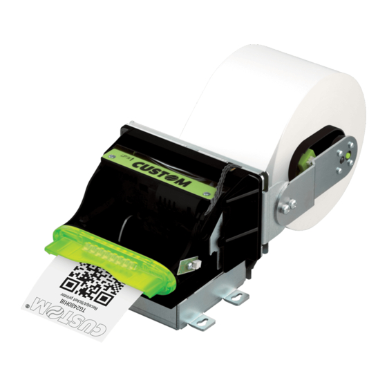
2 DESCRIPTION 2.1 Box contents Remove the device from its carton being careful not to damage the packing material so that it may be re-used if the device is to be transported in the future. Make sure that all the components illustrated below are present and that there are no signs of damage. If there are, contact customer service 1. -
Page 12: Device Components
2.2 Device components 1. Paper width adjustment 13. USB port 2. Paper roll holder pin 14. Status LED 3. Low paper sensor 15. Power supply port 4. Lever for paper stock adjustment 16. Serial port 5. Paper roll holder 17. Paper in 6. -
Page 13: Product Label
2.3 Product label PC = Product code (14 digits) SN = Serial number HW = Hardware release XXXXXXXXXXXXXX 0000000000000000000... -
Page 14: Key Functions: Power Up
2.4 Key functions: power up The following igure shows the functions of device’s keys according to the operating condition. POWER UP Hold down Hold down PRINT FEED PRINT FEED enter printing DEVICE TEST SETUP report Fast Fast push Fast push push PRINT FEED PRINT FEED PRINT FEED Logo Test Embedded Font Test: enter the select skip the - PC437 only... -
Page 15: Key Functions: Standby
2.5 Key functions: standby The following igure shows the functions of device’s keys according to the operating condition. STANDBY Fast push Fast push PRINT FEED PRINT FEED print Advance the paper demo ticket (preset length) -
Page 16: Status Messages
2.6 Status messages The status LED indicates hardware status of device. Given in the table below are the various LED signals and the cor- responding device status. STATUS LED DESCRIPTION DEVICE OFF GREEN DEVICE ON: NO ERROR RECEIVE DATA PRINTHEAD OVERHEATED PAPER END POWER SUPPLY VOLTAGE INCORRECT RECEPTION ERROR... -
Page 17: Installation
3 INSTALLATION 3.1 Panel fastening The device is provided with three ixing holes on the bottom of device (see following igure). To fasten the device on a panel, use three M3 screws (not included). All the dimensions shown in the following igure are in millimetres. 126.2 113.2 56.6 WARNING: In order to allow the anti-jamming system to operate properly, the device must be mounted on a perfectly horizontal plan. 0°... -
Page 18: Paper Roll Holder Assembly
3.2 Paper roll holder assembly The paper roll holder position is adjustable on four different positions: upper position P1, rotated upward P2, rear P3, rotated downward P4. Fix the paper roll holder to the device holes shown in igure according to the desired position by using the two M4x6 ixing screws supplied with the device. - Page 19 ATTENTION: While assembly the paper roll holder check the cable path (low paper sensor) is correct. Incorrect positions of the cable could cause damage on it.
-
Page 20: Connections
3.3 Connections The following igure shows the possible connections for the device. When the RS232 and USB communication cables are connected to the device at the same time, the communication take place via the USB port. Standard USB cable Power supply cable (included) Serial cable Power supply serial device USB device ATTENTION: In some using conditions, we recommend the installation of a ferrite core on the power supply cable. -
Page 21: Pinout
3.4 Pinout POWER SUPPLY Male Molex connector series 5569 vertical (n° 39-30-1020) 1 +VIN 2 GND ATTENTION: Respect power supply polarity. NOTE: Power supply cable The following igure shows the connector pinout of the power supply cable for the device: Female Molex connector Power supply cable series 5557 (n.39-01-3022) Cable Signal color +24 V Black USB INTERFACE Female USB type B connector... - Page 22 SERIAL INTERFACE Female RJ45 connector 1 n.c. 2 GND 3 TX (out) During transmission, takes the values -VRS232 and +VRS232 depending on data 4 RX (in) During reception, takes the values -VRS232 and +VRS232 depending on data 5 RT (out) When +VRS232, device is ready to receive data 6 n.c.
-
Page 23: Driver And Sdk
3.5 Driver and SDK In the website www.custom4u.it are available the drivers for the following operating system: OPERATING DESCRIPTION INSTALLATION PROCEDURE SYSTEM Driver for Windows XP Driver for Windows VISTA (32/64 bit) Driver for Windows 7 (32/64 bit) From the Start menu, press Run Driver for Windows 8 (32/64 bit) and type-in the path where the SW Windows... -
Page 25: Operation
4 OPERATION 4.1 Device opening Lift up the ejector group by unhooking the magnets on the bottom side and by rotating the group upwards. Widen the unlocking hook for the autocutter group. - Page 26 Rotate upwards the autocutter group to lift it up.
-
Page 27: Device Closing
4.2 Device closing Check the presence of paper scraps and remove them by using compressed air. Widen the unlocking hook and close the autocutter group. - Page 28 Lower the ejector group and hook the two magnets to the device chassis.
-
Page 29: Adjusting Paper Width
4.3 Adjusting paper width The device allows the use of paper roll width from 76 mm to 80 mm. Properly set the value of the “Paper Width” parameter during the setup procedure (see paragraph 5.5). To adjust the width of the paper roll case, rotate the knob as shown in the following igure. -
Page 30: Adjusting Paper Stock
4.4 Adjusting paper stock The device allows the move the position of the low paper sensor to adjust the amount of paper on the roll under which report the low paper. Use the lever shown in igure to move the low paper sensor: move the lever up to increase the paper stock, move the lever down to decrease the paper stock. -
Page 31: Switch The Device On
4.5 Switch the device on IN DC 24V 2.2Amax Power supply cable (included) EXTERNAL POWER SUPPLY (OPTIONAL) Connect the power supply cable to an external power supply unit and to the device. Use the type of electrical power supply indicated on the label. 24Vdc The green status LED turns on and the device is ready. -
Page 32: Loading The Paper Roll
4.6 Loading the paper roll To change the paper proceed as follows. At every change of paper, check inside the device. Adjust the paper stock Adjust the paper stock (see paragraph 5.4). (see paragraph 4.4). Inser the paper roll on the pin of the roll holder. Adjust the paper width Adjust the paper width (see paragraph 5.3). - Page 33 Power supply cable Switch on the device Switch on the device (see paragraph 4.5). (see paragraph 5.5). Insert the paper into the the input mouth so that it unrolls correctly, as shown in figure. ROOM Wait until the paper is automatically loaded and cut.
-
Page 34: Anti-Jamming System
4.7 Anti-jamming system The withdrawal of the ticket before the end of printing, may damage the printing mechanism or the paper ripping resulting in probable jam. The device is equipped with an anti-jamming system that starts operating when the user tries to pick up the ticket while printing is still in progress. -
Page 35: Configuration
5 CONFIGURATION 5.1 Coniguration by keys To enter the coniguration mode and print a setup report with the operating parameters of the device, proceed as follows. PRINT FEED While pressing the FEED key, switch on the device by inserting the power supply cable. PRINTER SETUP The device prints the report with parameters for settings. PRINT FEED Enter setup Press the FEED key to enter Hold down the FEED key to enter the coniguration mode (see paragraph the configuration mode (see paragraph 3.5). - Page 36 The following igure shows the setup report of the device. The shown values for parameters are sample values; for the list and the description of device parameters see the following paragraphs. DEVICE NAME AND < device name > FIRMWARE MODULES SCODE: <code> rel 1.00 RELEASE FCODE: <code> rel 1.00 LCODE: <code> rel 1.00 PRINTER SETTINGS PRINTER TYPE ........<device model> INTERFACE ..........RS232 PROGRAM MEMORY TEST....OK DYNAMIC RAM TEST......OK CUTTER TEST........OK...
-
Page 37: Coniguration By Software
5.2 Coniguration by software The setup parameters can be set by using the “PrinterSet” software tool available on www.custom4u.it. For a detailed description of the device operating parameters see the following paragraphs. To conigure the device by software, proceed as follows: Connect the device to a PC directly (see paragraph 3.3), Connect the device to a PC directly (see paragraph 4.5),... - Page 38 LOAD SAVE PORT SETUP FONTS UPGRADE H. reflect V. reflect Click on SETUP to access the operating parameteres of the device to be configured. PORT LOAD SAVE EXTRA SETUP <Parameter> Disabled Activation of the Bluetooth® module <Parameter> Enabled or WiFi on the device. If the “Wireless” parameter is set to ON (active) do not <Parameter>...
-
Page 39: Device Status
5.3 Device status The device operating status is indicated in the coniguration print-out in which, next to the name of the components dis- played, the following information is given: device model PRINTER TYPE INTERFACE interface present PROGRAM MEMORY TEST OK appears if functioning and NOT OK if faulty DYNAMIC RAM TEST OK appears if functioning and NOT OK if faulty CUTTER TEST OK appears if functioning and NOT OK if faulty voltage of the head... -
Page 40: Communication Parameters
5.4 Communication parameters The device allows the coniguration of the parameters listed in the following table. The parameters marked with the symbol are the default values. Settings remain active even after the device has been turned off and they are stored in non-volatile memory. RS232 BAUD RATE Communication speed of the serial interface: 9600 57600 19200... - Page 41 USB communication class deinition. USB CLASS Printer setting the printer function Virtual COM = setting the USB port as a virtual serial port...
-
Page 42: Operating Parameters
5.5 Operating parameters The device allows the coniguration of the parameters listed in the following table. The parameters marked with the symbol are the default values. Settings remain active even after the device has been turned off and they are stored in non-volatile memory. PRINTER EMULATION Available emulations for the device: CUSTOM/POS Printing mode: PRINT MODE Normal... - Page 43 Setting of printing speed and printing quality: SPEED / QUALITY Normal High Speed PRINT WIDTH Width of printing area: 76 mm 80 mm PAPER THRESHOLD Threshold value (in percent) for the recognition of the presence of paper by the paper presence sensor: PAPEREND BUFFER CLEAR Cleaning mode of the data in receive buffer, if the printing is stopped due to lack of paper: Disabled...
-
Page 44: Alignment Parameters
5.6 Alignment parameters This printer allows the coniguration of the parameters listed in the following table. The parameters marked with the symbol are the default values. Settings remain active even after the printer has been turned off and they are stored in non-volatile memory. BLACK MARK POSITION Management of the paper alignment: Disabled the black mark alignment is not performed Enabled =... - Page 45 Setting the digit for decimals: BLACK MARK DISTANCE [mm x 0.1] NOTE: For example, to set the black mark distance to 15 mm, modify the parameters as follows: Black Mark Distance Sign = + Black Mark Distance [mm x 10] Black Mark Distance [mm x 1] Black Mark Distance [mm x .1]...
-
Page 46: Hexadecimal Dump
5.7 Hexadecimal dump This function is used for the diagnosis of the characters received from the communications port. Characters are printed as hexadecimal code and the corresponding ASCII code (see below). Each line is preceded by a counter in hexadecimal that indicates the number of bytes received. -
Page 47: Alignment
6 ALIGNMENT The device is provided with a sensor for the use of alignment black mark in order to handle rolls of tickets with pre-printed ields and a ixed length. The alignment sensor is a “relection” sensor: this kind of sensor emits a band of light and detects the quantity of light relected to it. The presence of the black mark is therefore detected by the amount of light that returns to the sensor, con- sidering that the light is relected by the white paper and absorbed by the black mark. To ensure the correct alignment, you must enable the “Black Mark Position” parameter during the setup procedure (see paragraph 5.6). -
Page 48: Calibration
6.1 Calibration The sensor calibration occurs automatically and consists in adjusting the quantity of light emitted to match the degree of whiteness of the paper used and the degree of black of the mark printed on paper. The device automatically performs the self-calibration during the Setup procedure only if the “Black Mark Position” param- eter is set to a value other than “Disabled”... - Page 49 The following igure shows an example of paper with the non-thermal paper printed with black marks and other graphics (for example, a barcode): the outgoing voltage is constant while passing the white paper between two black marks, presents a peak at each black mark and presents some “noise” at each barcode. In this case, the optimal value for the “Black Mark Threshold”...
-
Page 50: Alignment Parameters
6.2 Alignment parameters The “alignment point” is deined as the position inside the ticket to use for the black mark alignment. The distance between the black mark edge and the alignment point is deined as “Black Mark Distance”. Referring to the front of the black mark, the value of “Black Mark Distance” varies from -19.9 mm minimum and +99.9 mm maximum. If the “Black Mark Distance” value is set to 0, the alignment point is set at the beginning of the black mark. Alignment point: Alignment Alignment... - Page 51 To set a negative value of the “Black Mark Distance” parameter is useful in cases where the alignment point refers to the black mark printed on the previous ticket or where the desired cutting line is placed in the middle of the alignment black mark.
- Page 52 To deine the alignment point you need to set the printer parameters that compose the numerical value of the “Black Mark Distance” parameter. (see paragraph 5.6). For example, to set a black mark distance of 15 mm between the black mark and the alignment point, the parameters must be set on the following values: Black Mark Distance sign Black Mark Distance [mm x 10] Black Mark Distance [mm x 1] Black Mark Distance [mm x .1] The “Black Mark Distance” parameter, may be modiied as described in chapter...
-
Page 53: Printing Area
6.3 Printing area In order to print ticket containing only one black mark and to not overlay printing to a black mark (that will make it useless for the next alignment), it is important to well calibrate the length of the printing area of ticket according to the inter-black mark distance. -
Page 55: Maintenance
7 MAINTENANCE 7.1 Paper jam Lift up the inspection door. Remove any scraps of paper from the front side of the device. - Page 56 Open the device Open the device (see paragraph 4.1). (see paragraph 5.1). Lift up the unlocking lever for the platen roller and remove any scraps of paper from the printing mechanism. Rotate clockwise the platen roller to eject the paper from the rear side of the device.
-
Page 57: Planning Of Cleaning Operations
7.2 Planning of cleaning operations The regular cleaning of the device keeps the print quality and extends its life. The following table shows the recommended planning for the cleaning operations. If you use the device in dusty environments, you must reduce the intervals between the cleaning operations. -
Page 58: Cleaning
7.3 Cleaning For periodic cleaning of the device, see the instructions below. Platen roller Autocutter Disconnect the power supply cable and Disconnect the power supply cable and Disconnect the power supply cable and Disconnect the power supply cable and open the device (see paragraph 4.1). open the device (see paragraph 4.1). - Page 59 Paper path Disconnect the power supply cable and Disconnect the power supply cable and open the device (see paragraph 4.1). open the device (see paragraph 4.1). ATTENTION: Do not use alcohol, solvents, or hard brushes. Do not let water or other liquids get inside the device. Alcohol, solvent Remove any scraps of paper and the accumulated paper dust under the inspection door...
- Page 60 Sensors Disconnect the power supply and Disconnect the power supply cable and open the inspection door (see paragraph 7.1). open the inspection door (see paragraph 7.1). ATTENTION: Do not use alcohol, solvents, or hard brushes. Do not let water or other liquids get inside the machine. Alcohol, solvent Clean the low paper sensor by using compressed air.
- Page 61 Chassis Disconnect the power supply cable. ISOPROPYL ALCOHOL ATTENTION: Do not use solvents, or hard brushes. Do not let water or other liquids get inside the machine. To clean the device, use compressed air or a soft cloth.
-
Page 62: Firmware Upgrade
7.4 Firmware upgrade Firmware upgrade can be performed by using the “PrinterSet” software tool available on www.custom4u.it. To upgrade irmware, proceed as follows: Login to the website www.custom4u.it, type in the product code of the device Login to the website www.custom4u.it, type in the product code of the device and download the latest irmware release available. - Page 63 LOAD SAVE PORT EXTRA HELP From Device From File Select a configuration file as follows: Click on LOAD > From device and select a device connected with the PC Click on LOAD > From file and select a .psc file on your PC Drag and drop a .psc file Click on LOAD >...
-
Page 65: Specification
8 SPECIFICATION 8.1 Hardware speciications GENERAL Paper input and alignment black mark presence, head temperature, Sensors paper jam, inspection door open, early withdrawal of the ticket, external low paper (on paper roll holder) Emulations TGH, CUSTOM/POS Windows XP Windows VISTA (32/64 bit) Windows 7 (32/64 bit) Windows 8 (32/64 bit) Printing driver... - Page 66 Printing width 76 mm, 80 mm Printing mode Normal, 90°, 180°, 270° Printing format Height/width from 1 to 8, bold, reverse, underlined, italic 55 character code tables (see paragraph 8.6) Character fonts Extended chinese GB18030-2000 Korean CP949 UPC-A, UPC-E, EAN13, EAN8, CODE39, ITF, CODABAR, Printable barcode CODE93, CODE128, CODE32, QRCODE, DATAMATRIX Normal = 95 mm/s...
- Page 67 DEVICE ELECTRICAL SPECIFICATIONS Power supply 24 Vdc ± 10% Medium consumption 2.2 A max Typical consumption 0.88 A Standby consumption 0.04 A ELECTRICAL SPECIFICATIONS POWER SUPPLY code 963GE020000053 (optional) Power supply voltage from 100 Vac to 240 Vac Frequency from 50 Hz to 60 Hz Output 24 V, 2.5 A Power...
-
Page 68: Character Speciications
8.2 Character speciications Character set Character density 11 cpi 15 cpi 20 cpi Number of columns Chars / seconds 1400 1960 2560 Lines / seconds Characters (L x H mm) - Normal 2.25 x 3 1.625 x 3 1.25 x 3 NOTE: Theoretical values. - Page 69 40.2 171.5 143.3 34.1 65.5...
-
Page 70: Power Supply, Power Cord And Adapter For Power Supply Dimensions
8.4 Power supply, power cord and adapter for power supply dimensions (optionals) The following table shows the dimensions of the power supply, the power cord and the adapter for power supply optionals for the device: POWER CORD code 26100000000311 Length 2000 mm ADAPTER FOR POWER SUPPLY code 26900000000005 Length... - Page 71 ADAPTER FOR POWER SUPPLY code 26900000000005 POWER SUPPLY code 963GE020000053 DC OUTPUT WIRE AC INLET 30 ± 0.50 127 ± 0.50 1500 ± 50 n.c. +24V...
-
Page 72: Paper Speciication
8.5 Paper speciication The following image shows an example of black mark placement on the non-thermal side of paper. All the dimensions shown in the following igure are in millimetres. 10.5 PAPER WIDTH = 80... -
Page 73: Character Sets
8.6 Character sets The device has 3 fonts of varying width (11, 15 and 20 cpi) which may be related one of the coding tables provided on the device. To know the coding tables actually present on the device, you need to print the font test (see paragraph 2.4). - Page 74 <CodeTable> Coding table PC855 - Cyrillic PC861 - Icelandic on request PC862 - Hebrew PC864 - Arabic PC869 - Greek on request ISO8859-2 - Latin 2 on request ISO8859-15 - Latin 9 on request PC1098 - Farsi PC1118 - Lithuanian on request PC1119 - Lithuanian on request...
-
Page 75: Consumables
9 CONSUMABLES The following table shows the list of available consumables for device: DESCRIPTION CODE 67300000000406 THERMAL PAPER ROLL width = 80 mm Ø external = 90 mm Ø core = 25 mm... -
Page 77: Accessories
10 ACCESSORIES The following table shows the list of available accessories for device: DESCRIPTION CODE 963GE020000053 POWER SUPPLY (for technical speciications, see paragraph 8.1) 26100000000311 POWER CORD SCHUKO PLUG length = 2 m (see paragraph 8.4) 26900000000005 ADAPTER CABLE FOR POWER SUPPLY length = 200 mm (see paragraph 8.4) - Page 78 21400000000040 DARK PAPER BEZEL 976CH010000001 KIT TICKET OUT 81300000000068 BOARD TOP BLACK MARK...
-
Page 79: Technical Service
11 TECHNICAL SERVICE In case of failure, contact the technical service accessing the website www.custom4u.it and using the support tools on the homepage. It is advisable to keep the identiication data of the product at hand. The product code, the serial number and the hardware release number can be found on the product label (see paragraph 2.3). - Page 80 CUSTOM S.p.A. World Headquarters Via Berettine, 2/B - 43010 Fontevivo, Parma ITALY Tel. +39 0521 680111 - Fax +39 0521 610701 info@custom.biz - www.custom.biz All rights reserved www.custom.biz...
Need help?
Do you have a question about the TG2480HIII and is the answer not in the manual?
Questions and answers