Table of Contents
Advertisement
Quick Links
VISIT VIKINGPUMP.COM FOR PDF OF CURRENT TSM ISSUE & TO VIEW REPAIR VIDEOS
TECHNICAL SERVICE MANUAL: INSTALLATION, OPERATION & MAINTENANCE
TABLE OF CONTENTS
Model Number Chart ..................................................................1
Introduction ................................................................................1
Safety Information & Instructions ...............................................2
Special Information ....................................................................3
Rotation ..................................................................................3
Pressure Relief Valves ...........................................................3
Maintenance ...............................................................................3
Cleaning Pump .......................................................................3
Storage ...................................................................................3
Suggested Repair Tools .........................................................3
Pump Disassembly ....................................................................6
Coupling Disassembly ...............................................................6
Disassembly: Bearing Housing ..................................................9
Assembly: Bearing Housing .......................................................9
Installation: Carbon Graphite Bushings ...................................10
Installation: Silicon Carbide Bushings......................................10
Pump Assembly .......................................................................10
Changing Pump Rotation .........................................................10
Coupling Assembly .................................................................. 11
Adjusting Head Gasket End Clearance ...................................13
Pressure Relief Valve Instructions ...........................................14
Disassembly .........................................................................14
Assembly ..............................................................................14
Pressure Adjustment ............................................................14
Important Ordering Information ............................................14
......................................................15
General Installation Notes ........................................................15
Foundation ...............................................................................16
Component & Unit Lifting Features .........................................16
Alignment .................................................................................18
Piping .......................................................................................18
Start Up ....................................................................................19
Troubleshooting .......................................................................20
Vacuum Gauge - Suction Port .............................................20
Pressure Gauge - Discharge Port ........................................20
Rapid Wear .............................................................................21
Preventative Maintenance .......................................................22
Do's & Don'ts ...........................................................................22
Installation ............................................................................22
Operation ..............................................................................22
Maintenance .........................................................................23
MOTOR SPEED PRODUCT LINE: STAINLESS STEEL
897 SERIES™
SIZES: GG, HJ, HL, AS, AK, AL
© 2019 Viking Pump, Inc. • Cedar Falls, IA
MODEL NUMBER CHART
Sealless Mag Drive
GG897
HJ897
HL897
AS897
AK897
AL897
INTRODUCTION
The illustrations used in this manual are for identification
purposes only and cannot be used for ordering parts.
Obtain a parts list from your Viking Pump
Always give a complete name of part, part number and
material with the model number and serial number of pump
when ordering repair parts. The unmounted pump or pump
unit model number and serial number are on the nameplate.
This manual only applies to the pump models specified in the
"Model Number Chart" on page 1. Pump specifications and
recommendations are listed in the Catalog Sections, which
are available at vikingpump.com.
⚠
WARNING !
Persons with surgical implants of a metallic or electronic
nature should avoid working on pump - especially the
inner magnet assembly.
This information must be read fully before beginning any
maintenance or repair of the pump. All maintenance or
repair must be done by SUITABLY TRAINED or qualified
persons only.
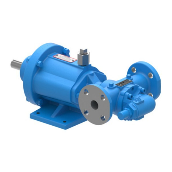
FIGURE 1:
GG, HJ, HL SIZES
TSM
1743
Page
1 of 24
Issue
A
representative.
®
FIGURE 2:
AS, AK, AL SIZES
Advertisement
Table of Contents

Subscribe to Our Youtube Channel
Related Manuals for Viking pump 897 Series


Summary of Contents for Viking pump 897 Series
-
Page 1: Table Of Contents
Vacuum Gauge - Suction Port ..........20 GG, HJ, HL SIZES AS, AK, AL SIZES Pressure Gauge - Discharge Port ........20 Rapid Wear ................21 Preventative Maintenance ............22 Do’s & Don’ts ................22 Installation ................22 Operation ................22 Maintenance .................23 © 2019 Viking Pump, Inc. • Cedar Falls, IA... -
Page 2: Safety Information & Instructions
BEFORE operating the pump, be sure that: information, refer to Appendix, General Installation Notes, • It is clean and free from debris. item 5 on Pressure Protection or contact your Viking Pump ® representative for Engineering Service Bulletin ESB-31. • All valves in the suction and discharge pipelines are fully opened. -
Page 3: Special Information
INTERNAL – Viking Part No. 2-810-047-999; EXTERNAL – Viking Part No. 2-810-029-375; 4. Feeler gauge set 5. Brass or plastic bar 6. Arbor press TSM 1743 | Issue A | Page 3 of 24 © 2019 Viking Pump, Inc. • Cedar Falls, IA... - Page 4 Insert Washer O-Ring for Head Pilot Capscrews for Relief Valve Capscrew for Inner Magnet Rotor and Shaft Assembly Internal Relief Valve TSM 1743 | Issue A | Page 4 of 24 © 2019 Viking Pump, Inc. • Cedar Falls, IA...
- Page 5 Capscrew for Motor or Bearing Carrier External Retaining Ring (4 Req’d) (2 Req’d for MD-A & MD-B) Canister Bearing Spacer Hand Knobs (MD-C) TSM 1743 | Issue A | Page 5 of 24 © 2019 Viking Pump, Inc. • Cedar Falls, IA...
-
Page 6: Pump Disassembly
The casing should be examined for wear, particularly in the area between the ports. All parts should be checked for wear Canister before the pump is put together. Retaining Rings TSM 1743 | Issue A | Page 6 of 24 © 2019 Viking Pump, Inc. • Cedar Falls, IA... - Page 7 Remove the external retaining rings from the shaft to remove the bearings. Do Not Place Fingers Here TSM 1743 | Issue A | Page 7 of 24 © 2019 Viking Pump, Inc. • Cedar Falls, IA...
- Page 8 5. Do not remove the o-ring unless it is bad, especially if PTFE (Derivative) Encapsulated. If a new o-ring is required, follow instructions in the “Pump Assembly” on page 10. TSM 1743 | Issue A | Page 8 of 24 © 2019 Viking Pump, Inc. • Cedar Falls, IA...
-
Page 9: Disassembly: Bearing Housing
Install the external retaining ring on the shaft of outer magnet assembly. Ball Bearings FIGURE 23 FIGURE 22 Press TSM 1743 | Issue A | Page 9 of 24 © 2019 Viking Pump, Inc. • Cedar Falls, IA... -
Page 10: Installation: Carbon Graphite Bushings
Set of Gaskets Includes .005 (1) .015 Outer Outer HJ, HL .005 (2) .007 Magnet Magnet (2) .005 AS, AK, AL .008 Assembly Assembly TSM 1743 | Issue A | Page 10 of 24 © 2019 Viking Pump, Inc. • Cedar Falls, IA... -
Page 11: Coupling Assembly
“Locked-out”. Check that pump rotates freely by spinning Required Required motor fan blades or bearing carrier shaft. Coupling Outer Magnet Outer Magnet Assembly Assembly TSM 1743 | Issue A | Page 11 of 24 © 2019 Viking Pump, Inc. • Cedar Falls, IA... - Page 12 Place the canister onto the pump and press on until it is in contact with the pump mounting flange. TSM 1743 | Issue A | Page 12 of 24 © 2019 Viking Pump, Inc. • Cedar Falls, IA...
-
Page 13: Adjusting Head Gasket End Clearance
5. Install the (4) 0.38” capscrew. Turn the output shaft over by hand to make sure the pump rotates freely. See “Figure 37” on page 13. TSM 1743 | Issue A | Page 13 of 24 © 2019 Viking Pump, Inc. • Cedar Falls, IA... -
Page 14: Pressure Relief Valve Instructions
4. Remove bonnet, spring guide, spring and poppet from valve body. Clean and inspect all parts for wear or damage and replace if necessary. TSM 1743 | Issue A | Page 14 of 24 © 2019 Viking Pump, Inc. • Cedar Falls, IA... -
Page 15: Appendix (Formerly Tsm 000)
Suction FIGURE A1 Relief Valve Adjusting Screw Cap (Should Always Point Toward Suction Port) FIGURE A2 Left-Hand Right-Hand Pump Pump TSM 1743 | Issue A | Page 15 of 24 © 2019 Viking Pump, Inc. • Cedar Falls, IA... -
Page 16: Foundation
(e). When the force exerted by the liquid under the poppet exceeds that exerted by the spring, the poppet lifts and liquid starts to flow through the valve. TSM 1743 | Issue A | Page 16 of 24 © 2019 Viking Pump, Inc. • Cedar Falls, IA... - Page 17 The slings can slide, allowing the unit to tip and/or fall. Improper lifts can result in personal injury and/or damage to the unit. TSM 1743 | Issue A | Page 17 of 24 © 2019 Viking Pump, Inc. • Cedar Falls, IA...
-
Page 18: Alignment
11. When fastening the piping to the pump it should not be necessary to impose any strain on the pump casing. “Springing” or “drawing” the piping up to the pump will TSM 1743 | Issue A | Page 18 of 24 © 2019 Viking Pump, Inc. • Cedar Falls, IA... -
Page 19: Start Up
Packing should weep a little to keep it cool and lubricated. 11. Do not use the Viking pump to flush, pressure test or prove the system with water. Either remove the pump or Obstruction Obstruction run piping around it while flushing or testing. -
Page 20: Troubleshooting
TROUBLESHOOTING h. Relief valve is set too high. 2. Low reading would indicate: A Viking pump that is properly installed and maintained will a. Relief valve is set too low. give long and satisfactory performance. b. Relief valve poppet is not seating properly. -
Page 21: Rapid Wear
See Rapid Wear Table. TSM 1743 | Issue A | Page 21 of 24 © 2019 Viking Pump, Inc. • Cedar Falls, IA... -
Page 22: Preventative Maintenance
Operation under either of these the pump. conditions may result in a heat build-up in the pump, which could cause hazardous conditions or happenings. TSM 1743 | Issue A | Page 22 of 24 © 2019 Viking Pump, Inc. • Cedar Falls, IA... -
Page 23: Maintenance
8. DON’T stick fingers in the ports of a pump. Serious injury may result. 9. DON’T spin the idler on the idler pin. Fingers may be jammed between teeth and crescent. TSM 1743 | Issue A | Page 23 of 24 © 2019 Viking Pump, Inc. • Cedar Falls, IA... - Page 24 (www.vikingpump.com/warranty/warranty-info). A complete non-self lubricating liquids, carbon graphite bushings are copy of the warranty may also be obtained by contacting Viking through regular mail at Viking Pump, Inc., 406 State typically the preferred material. Street, Cedar Falls, Iowa 50613, USA.
Need help?
Do you have a question about the 897 Series and is the answer not in the manual?
Questions and answers