Advertisement
Table of Contents
Electronic copies of the most current TSM issue can be found on the Viking Pump website at www.vikingpump.com
CONTENTS
Special Information . . . . . . . . . . . . . . . . . . . 3
Maintenance . . . . . . . . . . . . . . . . . . . . . . 3
Disassembly . . . . . . . . . . . . . . . . . . . . . . 4
Assembly . . . . . . . . . . . . . . . . . . . . . . . . 5
Mechanical Seal Replacement . . . . . . . . . . . . . 6
Seal Removal. . . . . . . . . . . . . . . . . . . . . 6
Seal Installation. . . . . . . . . . . . . . . . . . . . 7
Thrust Bearing Adjustment . . . . . . . . . . . . . . . 8
Installation of Carbon Graphite Bushings . . . . . . . . 9
Pressure Relief Valve Instructions . . . . . . . . . . . 9
Disassembly . . . . . . . . . . . . . . . . . . . . .10
Assembly . . . . . . . . . . . . . . . . . . . . . . .10
Pressure Adjustment . . . . . . . . . . . . . . . . .10
Heat Cartridges . . . . . . . . . . . . . . . . . . . . .10
INTRODUCTION
The illustrations used in this manual are for identification
purposes only and cannot be used for ordering parts. Obtain
a parts list from a Viking representative. Always give a
complete name of part, part number and material with the
model number and serial number of pump when ordering
repair parts. The unmounted pump or pump unit model
number and serial number are on the nameplate.
In the Viking model number system, basic size letters are
combined with series number (124A, 4124A, 4124AE, 126A,
4126A, 124AE, 124E, 123A, 4123A, 127A, 4127A, 224A,
4224A, 224AE, 4224AE, 226A, 4226A, 223A, 4223A, 227A,
4227A) indicating basic pump construction and material.
Model Chart Number
UNMOUNTED PUMP
Non-Jacketed
Jacketed
Packed
Mech. Seal
Packed Mech. Seal
LS124A
LS4124A
LS224A
LS124E
LS126A
LS4126A
LS226A
LS123A
LS4123A
LS223A
LS127A
LS4127A
LS227A
Q124A
Q4124A
Q224A
Q124E
Q126A
Q4126A
Q226A
Q123A
Q4123A
Q223A
Q127A
Q4127A
Q227A
QS124A
QS4124A
QS124E
QS126A
QS4126A
QS226A
QS123A
QS4123A
QS223A
QS127A
QS4127A
QS227A
M124A
M4124A
M224A
VIKING PUMP, INC. • A Unit of IDEX Corporation • Cedar Falls, IA 50613 USA
TECHNICAL SERVICE MANUAL
TECHNICAL SERVICE MANUAL
UNIVERSAL SEAL HEAVY DUTY PUMPS
SERIES 124A/AE, 4124A/AE, 124E, 224A, & 4224A CAST IRON
SERIES 126A, 4126A, 226A & 4226A DUCTILE IRON
SERIES 123A, 4123A, 223A & 4223A STEEL
SERIES 127A, 4127A, 227A & 4227A STAINLESS STEEL
UNITS
LS4224A
Units are designated
by
the
unmounted
LS4226A
pump model numbers
LS4223A
followed by a letter
LS4227A
indicating drive style.
Q4224A
V = V-Belt
Q4226A
D = Direct Connected
Q4223A
R = Viking Speed
Q4227A
Reducer
P = Commercial
Speed Reducer
QS4226A
QS4223A
QS4227A
M224A
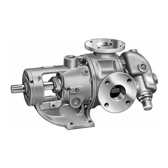
SIZES LS, Q, QS & M
FIGURE 1
Size LS illustrated
(Shown with jacketed bracket and relief valve)
FIGURE 2
Size Q illustrated
(Non-Jacketed)
FIGURE 3
Size QS illustrated
(Non-Jacketed)
A = Universal Seal Pump
AE = Universal Seal Pump with larger rotor shaft (L, LQ, LL only)
E = Universal Seal with electric heating
SECTION
TSM 630.2
PAGE
1 OF 12
ISSUE
K
Advertisement
Table of Contents

Subscribe to Our Youtube Channel
Related Manuals for Viking pump 124A Series


Summary of Contents for Viking pump 124A Series
-
Page 1: Table Of Contents
Electronic copies of the most current TSM issue can be found on the Viking Pump website at www.vikingpump.com TECHNICAL SERVICE MANUAL TECHNICAL SERVICE MANUAL UNIVERSAL SEAL HEAVY DUTY PUMPS SECTION TSM 630.2 SERIES 124A/AE, 4124A/AE, 124E, 224A, & 4224A CAST IRON... - Page 2 ● You know what material the pump has been For weight of the pump alone (which does not include handling, have obtained a material safety data the drive and/or base plate) refer to the Viking Pump sheet (MSDS) for the material, and understand product catalog.
-
Page 3: Special Information
Viking pumps are designed for long, trouble-free service life DANGER ! under a wide variety of application conditions with a minimum of maintenance. The points listed below will help provide long Before opening any Viking pump liquid chamber service life. (pumping chamber,... -
Page 4: Disassembly
Avoid damaging head gasket. If pump is furnished DANGER ! with pressure relief valve, it need not be removed from head or disassembled at this point. Refer to Pressure Before opening any Viking pump liquid chamber Relief Valve Instructions, page 9. (pumping chamber,... -
Page 5: Assembly
BRACKET BALL BEARING BEARING HOUSING BEARING HOUSING SETSCREW SETSCREW SPACER COLLAR SPACER COLLAR SPACER SHAFT COLLAR SHAFT LIPSEAL LIPSEAL END CAP LIPSEAL SETSCREW TAPERED ROLLER BEARING END CAP SETSCREW FIGURE 6 Q-M BEARING HOUSING ASSEMBLY HALF ROUND RINGS FIGURE 5 LS BEARING HOUSING ASSEMBLY 8. -
Page 6: Mechanical Seal Replacement
Failure to tighten locknut or engage lockwasher tang could result in early bearing failure DANGER ! and cause damage to rest of pump. Remove length of Before opening any Viking pump liquid chamber hardwood or brass from port opening. (pumping chamber,... -
Page 7: Seal Installation
CARTRIDGE TYPE CIRCULATION LINE Cartridge mechanical seals are designed so that they may CONNECTION MECHANICAL SEAL be replaced with minimal pump and piping disassembly. The SEAL ACCESS (ROTARY MEMBER) seal may be accessed by removing the bearing housing. HOLE (See Disassembly, Steps 3-5, page 4). 1. -
Page 8: Thrust Bearing Adjustment
FLUSH CONNECTION NOTE: Some PTFE wedge seals are equipped with holding clips, which compress the seal springs. Remove SEAL ACCESS HOLE holding clips to release springs after seal is installed on MECHANICAL SEAL shaft. (ROTARY MEMBER) 5. Move rotary member so set screws are directly below seal access holes on side of bracket (See Figure 9, page 7 and Figure 10). -
Page 9: Installation Of Carbon Graphite Bushings
Carbon graphite bushings with extra interference fits are TURN BRG. ADDITIONAL frequently furnished for high temperature operation. These STANDARD HOUSING LENGTH ON bushings must be installed by a shrink fit. PUMP C.C.W. O.D. BRG. MODEL SIZE CLEARANCE LENGTH ON HOUSING FOR 1. -
Page 10: Heat Cartridges
DISASSEMBLY 1. Spacers should be installed between the foot of the pump and the base. This will create an air gap between the Mark valve and head before disassembly to insure proper pump and base to limit heat transfer to the base. reassembly. - Page 11 NOTE: 1. Heat cartridges, temperature probes, and controllers must 7. Do not use heat cartridges with different watt densities be wired by a licensed electrician to meet local codes. from those supplied by Viking. Changing watt densities may result in localized over or under heating. 2.
- Page 12 OR PLACED ON NOTICE OF THE POSSIBILITY OF SUCH DAMAGES AND NOTWITHSTANDING THE FAILURE OF ANY ESSENTIAL PURPOSE OF ANY PRODUCT. © 8/2017 Viking Pump Inc. VIKING PUMP, INC. • A Unit of IDEX Corporation • Cedar Falls, IA 50613 USA All rights reserved...
Need help?
Do you have a question about the 124A Series and is the answer not in the manual?
Questions and answers