Table of Contents
Advertisement
Quick Links
Advertisement
Table of Contents

Subscribe to Our Youtube Channel
Related Manuals for National Instruments 9918


Summary of Contents for National Instruments 9918
- Page 1 NI-9918...
-
Page 2: Safety Guidelines
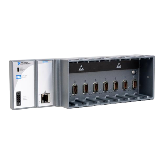
USER MANUAL AND SPECIFICATIONS NI 9148 Ethernet Expansion Chassis for C Series Modules This document describes how to connect the NI 9148 to a network and how to use the NI 9148 features. This document also contains specifications for the NI 9148. Figure 1. -
Page 3: Safety Guidelines For Hazardous Locations
Do not operate the NI 9148 in a manner not specified in this document. Caution Product misuse can result in a hazard. You can compromise the safety protection built into the product if the product is damaged in any way. If the product is damaged, return it to NI for repair. -
Page 4: Electromagnetic Compatibility Guidelines
Do not install a device if it appears damaged in any way. Note Unpack any other items and documentation from the kit. Store the device in the antistatic package when the device is not in use. NI 9148 User Manual | © National Instruments | 3... -
Page 5: Mounting The Chassis
What You Need to Install the NI 9148 • NI 9148 Ethernet Expansion Chassis • NI-RIO Software DVD • C Series I/O modules • DIN rail mount kit (for DIN rail mounting only) • Panel mount kit (for panel mounting only) •... - Page 6 Fasten the chassis to the panel mount kit using a number 2 Phillips screwdriver and two M4 × 25 screws. National Instruments provides these screws with the panel mount kit. NI 9148 User Manual | © National Instruments | 5...
-
Page 7: Mounting The Chassis On A Din Rail
You must use these screws because they are the correct depth and thread for the panel. Tighten the screws to a maximum torque of 1.3 N · m (11.5 lb · in.). Figure 5. Installing the Panel Mount Accessory on the NI 9148 Figure 6. - Page 8 Press down firmly on the chassis to compress the spring until the clip locks in place on the DIN rail. Make sure that no I/O modules are in the chassis before removing it Caution from the DIN rail. NI 9148 User Manual | © National Instruments | 7...
- Page 9 Installing C Series I/O Modules in the Chassis The following figure shows the mechanical dimensions of C Series I/O modules. Figure 9. C Series I/O Module, Front and Side View with Dimensions 88.1 mm (3.47 in.) 22.9 mm 70.7 mm (0.9 in.) (2.78 in.) Make sure that no I/O-side power is connected to the I/O module.
- Page 10 Connect the chassis to an Ethernet network using Ethernet port 1 on the front panel. Use a standard Category 5 (CAT-5) or better shielded, twisted-pair Ethernet cable to connect the chassis to an Ethernet hub or a computer. NI 9148 User Manual | © National Instruments | 9...
-
Page 11: Wiring Power To The Chassis
To prevent data loss and to maintain the integrity of your Ethernet Caution installation, do not use a cable longer than 100 m. If you need to build your own cable, refer to the Cabling section for more information about Ethernet cable wiring connections. -
Page 12: Configuring Ip Settings
Select the chassis under Remote Systems to see the Network Settings tab in the middle pane of MAX. Enter a name for the chassis in the Name field. NI 9148 User Manual | © National Instruments | 11... -
Page 13: Configuring Dip Switches
Select settings for the chassis in the IP Settings section, then click Apply. For information about configuring network settings, refer to the Note Configuring Network Settings book of the MAX Remote Systems Help. In MAX, click Help»Help Topics»Remote Systems. On the Contents tab, browse to LabVIEW Real-Time Target Configuration»Configuring Network Settings. -
Page 14: Understanding Led Indications
The STATUS LED is off during normal operation. The NI 9148 indicates specific error conditions by flashing the STATUS LED a certain number of times every few seconds, as shown in the following table. NI 9148 User Manual | © National Instruments | 13... - Page 15 The software has crashed twice without rebooting or cycling power between crashes. This usually occurs when software on the chassis is corrupted. Reinstall software on the chassis. If the problem persists, contact National Instruments. Continuous The device may be configured for DHCP but unable to get an IP address flashing or solid because of a problem with the DHCP server.
-
Page 16: Power Requirements
If you need to clean the NI 9148, wipe it with a dry towel. For two-dimensional drawings and three-dimensional models of the NI 9148, ni.com/dimensions visit and search by module number. Weight (unloaded) 929 g (32.7 oz) NI 9148 User Manual | © National Instruments | 15... -
Page 17: Safety Voltages
Screw-terminal wiring Gauge 0.2 mm to 2.1 mm (24 AWG to 14 AWG) copper conductor wire Wire strip length 6 mm (0.24 in.) of insulation stripped from the Temperature rating 85 °C Torque for screw terminals 0.20 N · m to 0.25 N · m (1.8 lb · in. to 2.2 lb ·... -
Page 18: Electromagnetic Compatibility
To obtain product certifications and the DoC for this product, visit certification, search by model number or product line, and click the appropriate link in the Certification column. NI 9148 User Manual | © National Instruments | 17... -
Page 19: Hazardous Locations
The following table shows the standard Ethernet cable wiring connections for both normal and crossover cables. Use NI 9917 and NI 9918 industrial enclosures to protect the device in harsh, dirty, or wet environments. 18 | ni.com | NI 9148 User Manual... -
Page 20: Environmental Management
For additional environmental information, refer to the Minimize Our Environmental Impact web page at ni.com/environment. This page contains the environmental regulations and directives with which NI complies, as well as other environmental information not included in this document. NI 9148 User Manual | © National Instruments | 19... -
Page 21: Worldwide Support And Services
Battery Directive replace it, use the Return Material Authorization (RMA) process or contact an Cd/Hg/Pb authorized National Instruments service representative. For more information about compliance with the EU Battery Directive 2006/66/EC about Batteries and Accumulators and Waste Batteries and Accumulators, visit ni.com/environment/... - Page 22 CONTAINED HEREIN AND SHALL NOT BE LIABLE FOR ANY ERRORS. U.S. Government Customers: The data contained in this manual was developed at private expense and is subject to the applicable limited rights and restricted data rights as set forth in FAR 52.227-14, DFAR 252.227-7014, and DFAR 252.227-7015. © 2010—2016 National Instruments. All rights reserved. 375519C-01 Apr16...
Need help?
Do you have a question about the 9918 and is the answer not in the manual?
Questions and answers