National Instruments NI 9144 User Manual
Deterministic ethernet expansion chassis for c series modules
Hide thumbs
Also See for NI 9144:
- User manual (65 pages) ,
- User manual (20 pages) ,
- Getting started manual (13 pages)
Table of Contents
Advertisement
USER GUIDE AND SPECIFICATIONS
NI 9144
Deterministic Ethernet Expansion Chassis for C Series Modules
This user guide describes how to connect the NI 9144 chassis to a network, how to use the
NI 9144 chassis features, and contains the NI 9144 chassis specifications. The NI 9144 is a slave
device and requires a compliant EtherCAT Master and network to function.
4
1
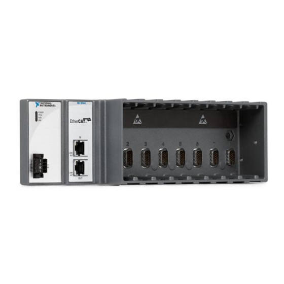
LEDs
2
IN Port
Figure 1. NI 9144 Chassis
1
POWER
FPGA
RUN
ERR
V
INPUT
C
9-30 V
NC
20 W MAX
C
NI 9144
Ether
IN
LINK/
ACT
LINK/
ACT
OUT
3
OUT Port
4
Power Connector
2
3
Advertisement
Table of Contents

Related Manuals for National Instruments NI 9144


Summary of Contents for National Instruments NI 9144
- Page 1 Deterministic Ethernet Expansion Chassis for C Series Modules This user guide describes how to connect the NI 9144 chassis to a network, how to use the NI 9144 chassis features, and contains the NI 9144 chassis specifications. The NI 9144 is a slave device and requires a compliant EtherCAT Master and network to function.
-
Page 2: Table Of Contents
Safety Guidelines for Hazardous Locations The NI 9144 chassis is suitable for use in Class I, Division 2, Groups A, B, C, D, T4 hazardous locations; Class I, Zone 2, AEx nA IIC T4 and Ex nA IIC T4 hazardous locations; and nonhazardous locations only. -
Page 3: Special Conditions For Hazardous Locations Use In Europe
DC mains supply or any supply requiring a connecting cable longer than 3 m (10 ft.). A DC mains supply is a local DC electricity supply network in the infrastructure of a site or building. NI 9144 User Guide and Specifications | © National Instruments | 3... -
Page 4: Special Guidelines For Marine Applications
Figure 2. NI 9144 Chassis, Bottom View with Dimensions 48.4 mm Cabling Clearance (1.9 in.) 29.0 mm 50.8 mm (2.00 in.) (1.14 in.) 58.9 mm (2.32 in.) 286.4 mm (11.28 in.) 3.2 mm (0.13 in.) 4 | ni.com | NI 9144 User Guide and Specifications... - Page 5 After the chassis is mounted, you will not be able to read the serial number. Remove any C Series I/O modules from the chassis before mounting it. Caution NI 9144 User Guide and Specifications | © National Instruments | 5...
-
Page 6: Mounting The Ni 9144 Chassis On A Panel
Mounting the NI 9144 Chassis on a Panel Use the NI 9905 panel mount kit to mount the NI 9144 chassis on a flat surface. To use the NI 9905 panel mount kit, complete the following steps: Fasten the chassis to the panel mount kit using a number 2 Phillips screwdriver and two M4 ×... -
Page 7: Mounting The Chassis On A Din Rail
DIN rail: Fasten the DIN rail clip to the chassis using a number 2 Phillips screwdriver and two M4 × 16 screws. National Instruments provides these screws with the DIN rail mount kit. Figure 7. Installing the DIN Rail Clip on the NI 9144 Chassis... -
Page 8: Connecting The Ni 9144 Chassis To A Network
LabVIEW Real-Time target to the NI 9144 IN port. Use a standard Category 5 (CAT-5) or better Ethernet cable. Use the NI 9144 OUT port to connect to other NI 9144 chassis and slave devices on the same segment. -
Page 9: Understanding Led Indications
You can program this LED using LabVIEW FPGA. RUN and ERR LEDs The RUN LED is green and indicates that the NI 9144 is in an operational state. The ERR (error) LED is red and indicates an error. Table 1 lists the RUN and ERR LED indications. - Page 10 Firmware update Booting Error Corrupt firmware or hardware error Figure 10 shows the Run Mode transition. Figure 10. EtherCAT Modes INIT LabVIEW Configuration Mode PRE-OP Bootstrap SAFE-OP Operational LabVIEW Active Mode 10 | ni.com | NI 9144 User Guide and Specifications...
-
Page 11: Resetting The Ni 9144 Network Configuration
LabVIEW Active Mode to the LabVIEW Configuration Mode, during normal operation or in case of a serious error, the NI 9144 passes through this EtherCAT safe state. The EtherCAT safe state forces the data of output modules to pre-defined safe values, which are set by default to output zero volts for the default channel configuration. -
Page 12: How To Upgrade Your Firmware
To upgrade your firmware to a new version or reset your device to the factory state, complete the following steps: Discover your real-time target and NI 9144 chassis. Right-click the RT target and select Deploy All, as shown in Figure 11. Figure 11. Deploy All 12 | ni.com | NI 9144 User Guide and Specifications... - Page 13 After a successful deployment, change the controller to Configuration Mode. Right-click the RT target and select Utilities»Scan Engine Mode»Switch to Configuration, as shown in Figure 12. Figure 12. Switch to Configuration NI 9144 User Guide and Specifications | © National Instruments | 13...
-
Page 14: Using The Ni 9144 With An Ethercat Third-Party Master
All of the functionality of the NI C Series modules is available to third-party masters using vendor extensions to the object dictionary. The NI 9144 is a modular device, meaning each module plugged into the backplane has its own object dictionary, and each module configuration is done through this dictionary. -
Page 15: Using Aoe/Sdo
For more information, refer to your C Series module documentation. Using CoE/SDO The CoE protocol does not have a destination port or address, so the NI 9144 provides an object dictionary entry that allows addressing support. Prior to sending an SDO or SDOInfo request, your application can write a slot number of one through eight to the object dictionary index 0x5FFF subindex 0. -
Page 16: Safety And Hazardous Locations Standards
• IEC 61010-1, EN 61010-1 • UL 61010-1, CSA 61010-1 • EN 60079-0:2012, EN 60079-15:2010 • IEC 60079-0: Ed 6, IEC 60079-15: Ed 4 16 | ni.com | NI 9144 User Guide and Specifications... - Page 17 Ex nA IIC T4 Europe (DEMKO) ..........Ex nA IIC T4 Gc Environmental The NI 9144 chassis is intended for indoor use only, but it may be used outdoors if mounted in a suitably rated enclosure. Operating temperature (IEC 60068-2-1, IEC 60068-2-2) ..... -40 °C to 70 °C...
- Page 18 Table 2 shows the standard Ethernet cable wiring connections. Table 2. Ethernet Cable Wiring Connections Connector 1 Connector 2 white/orange white/orange orange orange white/green white/green blue blue white/blue white/blue green green white/brown white/brown brown brown 18 | ni.com | NI 9144 User Guide and Specifications...
- Page 19 Group 1 equipment (per CISPR 11) is any industrial, scientific, or medical Note equipment that does not intentionally generate radio frequency energy for the treatment of material or inspection/analysis purposes. NI 9144 User Guide and Specifications | © National Instruments | 19...
- Page 20 National Instruments WEEE initiatives, and compliance with WEEE Directive 2002/96/EC on Waste and Electronic Equipment, visit ni.com/environment/ weee National Instruments (RoHS) National Instruments RoHS ni.com/ (For information about China RoHS compliance, environment/rohs_china go to ni.com/environment/rohs_china 20 | ni.com | NI 9144 User Guide and Specifications...
-
Page 21: Appendix
Vendor Extensions to the Object Dictionary Most object dictionary entries are defined by the relevant EtherCAT and CANOpen specification for modular slave devices. Both the NI 9144 device and the C Series modules have vendor extensions to the standard. These extensions are described here. - Page 22 0x5FFF Slot address override. To address CoE requests to a given module’s object dictionary, enter the module’s slot number here. Write a 0 here to cancel the slot address override. 22 | ni.com | NI 9144 User Guide and Specifications...
- Page 23 — Safe data values that mirror the … PDO data in 0x6000…0x67FF. 0x47FF 0x4800 — — Safe control values that mirror the … SDO data in 0x2000…0x27FF. 0x4FFF NI 9144 User Guide and Specifications | © National Instruments | 23...
-
Page 24: Supported C Series Modules
• NI 9264 • NI 9265 • NI 9269 • NI 9381 • NI 9401 • NI 9402 • NI 9403 • NI 9476 • NI 9478 • NI 951x 24 | ni.com | NI 9144 User Guide and Specifications... - Page 25 On the NI 9201/9221, this conversion code is a bit flag where bit 0 represents a conversion on channel 0, through bit 7 for channel 7. NI 9144 User Guide and Specifications | © National Instruments | 25...
- Page 26 V corrected V raw V raw bits LSB weight Offset nV --------- - ------ - – ------ - bits 26 | ni.com | NI 9144 User Guide and Specifications...
- Page 27 — Calibration = 36 Bipolar Offset Ch0 Bipolar Gain Ch1 Gain — — Ch7 Gain Unipolar Offset Ch0 Unipolar Gain — — External Calibration, Bipolar Gain — — NI 9144 User Guide and Specifications | © National Instruments | 27...
- Page 28 0b111 = 7 For example, the scan list entry 0x00010006 indicates that this scan gets stored at address 1, and the conversion two is a bipolar channel 3 (3 reversed = 6). 28 | ni.com | NI 9144 User Guide and Specifications...
- Page 29 The calibration data is stored in a U32 array, though each offset should be interpreted as a signed value. Table 12. NI 9203 Calibration Coefficients Coefficient Representation Units LSB Weight Unsigned pA/LSB Offset Signed NI 9144 User Guide and Specifications | © National Instruments | 29...
- Page 30 The vendor configuration extensions for the NI 9205/9206 are listed in Table 14. Table 14. NI 9205/9206 Vendor Configuration Extensions Index Type Description 0x2001 ARR:U32 — Scan List = 33 Channels to Convert = <1..32>, default = 32 2..33 Channel Code 30 | ni.com | NI 9144 User Guide and Specifications...
- Page 31 The scan list channel codes consist of eight bit fields in a 32-bit entry. Table 15. Scan List Format Bits Field 31..24 23..16 Data Offset[t] 15..0 Conversion Code[t+2} NI 9144 User Guide and Specifications | © National Instruments | 31...
- Page 32 10 = Single-End A (Ch. <0..7>, <16..23>) 11 = Single-End B (Ch. <8..15>, <24..31>) 1..0 00 = ±10 V 01 = ±5 V 10 = ±1 V 11 = ±200 mV 32 | ni.com | NI 9144 User Guide and Specifications...
- Page 33 Convert the 32-bit hex values to 64-bit floating point format for use in the calibration formula. Select the 32-bit gain value for a particular range. Select the 32-bit offset value (to be interpreted as a signed int) for a particular range. NI 9144 User Guide and Specifications | © National Instruments | 33...
- Page 34 NI 9207 Conversion Speed Control The NI 9207 converts at two pre-defined rates, as controlled by the speed control field. The conversion rate assumes that 16 channels are in the scan list. Note 34 | ni.com | NI 9144 User Guide and Specifications...
- Page 35 ARR:U32 — Scan List = 17 Channels to Convert = <1..16>, default = 16 2..17 Channel Code 0x2002 Conversion Speed Control = 0 or 1, default = 0 NI 9144 User Guide and Specifications | © National Instruments | 35...
- Page 36 Calibration data is set up by driver during initialization, and the calibration conversion is performed on the module ADC itself. Thus, you do not need to use the calibration tables. 36 | ni.com | NI 9144 User Guide and Specifications...
- Page 37 Value 0x2001 ARR:U32 NI 9211 Calibration Data Calibration data is set up by the driver during initialization, and the calibration conversion is performed on the module ADC itself. NI 9144 User Guide and Specifications | © National Instruments | 37...
- Page 38 The error/status field is defined as listed in Table 28. Table 28. NI 9212 Open Thermocouple Status Code Bits Field 31..8 Reserved 7..0 The latest detected open thermocouple status. Each channel takes one bit. 38 | ni.com | NI 9144 User Guide and Specifications...
- Page 39 = 18 2..19 Channel Code 0x2002 Channel Speed Control = 2 or 15, default = 2 0x2003 Common Mode Range Error Detection Status (also as 8-bit PDO) NI 9144 User Guide and Specifications | © National Instruments | 39...
- Page 40 <0..15>: sixteen thermocouple channels (always measured in a ±78.125 mV range) • 16: one cold junction channel (always measured in a ±2.5 V range) • 17: one auto zero channel (always measured in a ±78.125 mV range) 40 | ni.com | NI 9144 User Guide and Specifications...
- Page 41 × ------------------------------------------------------------ - – TCvoltage autozero where represents raw TC voltage TCvoltage represents binary bits for the TC represents binary bits returned by the auto zero channel autozero NI 9144 User Guide and Specifications | © National Instruments | 41...
- Page 42 Scan List = 21 Channels to Convert = 1..20, default = 20 2..21 Channel Code 0x2002 Conversion Speed Control/Open Thermocouple Detection 0x2003 Common Mode Range Error Detection Status (also as 8-bit PDO) 42 | ni.com | NI 9144 User Guide and Specifications...
- Page 43 17: Cold junction channel 0 (always measured in a ±2.5 V range) • 18: Cold junction channel 1 (always measured in a ±2.5 V range) • 19: Cold junction channel 2 (always measured in a ±2.5 V range) NI 9144 User Guide and Specifications | © National Instruments | 43...
- Page 44 After calculating the CJC and the TC voltage, use the NI 9214 Getting Started.lvproj located by default in the directory LabVIEW\examples\CompactRIO\Module Specific to calculate the resistance of the thermistor and the CJC temperature in degrees Celsius. 44 | ni.com | NI 9144 User Guide and Specifications...
- Page 45 The calibration data is stored in a U32 array, though each Offset field (subindex 1, 3, 5, and so on) should be interpreted as a signed value. Table 40. NI 9215 Calibration Coefficients Coefficient Representation Units LSB Weight Unsigned nV/LSB Offset Signed NI 9144 User Guide and Specifications | © National Instruments | 45...
- Page 46 Conversion Speed Control = 2 or 31, default = 31 0x2100 ARR:U32 — Calibration = 16 Ch0 Offset Ch0 Gain Ch1 Offset — — Ch3 Gain External Ch0 Offset — — 46 | ni.com | NI 9144 User Guide and Specifications...
- Page 47 Note speed control in 0x2002. For example, the scan list entry 0x00000001FC indicates this scan stores at address 1, and the next conversion is channel 2 at high-accuracy. NI 9144 User Guide and Specifications | © National Instruments | 47...
- Page 48 – ------- - μΩ bits pΩ where (bits) represents data returned by the NI 9217 in bits represents calibrated resistance reading corrected 48 | ni.com | NI 9144 User Guide and Specifications...
- Page 49 Ch0 22 mV/V Gain External Ch0 Offset — — NI 9218 Configure Module This module is set to maximum speed and configured for Full-Bridge mode for all channels by default. NI 9144 User Guide and Specifications | © National Instruments | 49...
- Page 50 The NI 9218 divides the clock source by this value and uses it as the converters’ oversample clock. The data rate is equal to 1/256 times this oversample clock frequency. 1..0 Clock Source — 50 | ni.com | NI 9144 User Guide and Specifications...
- Page 51 Table 50. NI 9218 Example Data Rates Oversample Data Rate Clock Divisor Clock Source Clock Rate 51.2 kS/s 13.1072 MHz 25.6 kS/s 6.5536 MHz 17.067 kS/s 4.3691 MHz 1.652 kS/s 422.8129 kHz NI 9144 User Guide and Specifications | © National Instruments | 51...
- Page 52 ADC data x represents raw data for the voltage, current, or bridge b represents the Offset value 52 | ni.com | NI 9144 User Guide and Specifications...
- Page 53 Ch0 15 V Offset — — Ch0 Full Bridge 7.8m V-V Gain Ch1 60 V Offset — — 0x2101 ARR:U32 External Calibration = 168 — Ch0 60 V Offset NI 9144 User Guide and Specifications | © National Instruments | 53...
- Page 54 LSB weight, which is the number of volts per bit, and an offset, which is the number of volts per bit measured when the inputs are grounded. LSB weight is referred to as Gain in the object dictionary. Note 54 | ni.com | NI 9144 User Guide and Specifications...
- Page 55 10 kΩ 1 kΩ Thermocouple — 4-Wire RTD Pt1000 Pt100 3-Wire RTD Pt1000 Pt100 Quarter-Bridge 350 Ω 120 Ω Half-Bridge ±500 mV/V Reserved — Full-Bridge ±62.5 mV/V ±7.8 mV/V NI 9144 User Guide and Specifications | © National Instruments | 55...
- Page 56 0x78, 0x56, 0x34, 0x12. The command word format is shown in Table 56. Table 56. NI 9219 Command Word Format Bits Field 31..24 Reserved 23..16 15..8 Configuration Data 7..0 Configuration Command 56 | ni.com | NI 9144 User Guide and Specifications...
- Page 57 Range, and Calibration Gain/Offset values for each channel on the NI 9219. You must first send calibration gain and offset values in MSB format. The Note Conversion Time value must be the same across all channels. NI 9144 User Guide and Specifications | © National Instruments | 57...
- Page 58 When any AI data channel is configured for Thermocouple, ADC conversion Note time increases by 10 ms for all channels. Refer to Max Frequency in Table 58 for various ACD timing configurations. The TC mode/range configuration code is 0x0A. 58 | ni.com | NI 9144 User Guide and Specifications...
- Page 59 Pt100 4w 0x0D Pt1000 3w 0x0E Pt100 3w 350 Ω 0x0F Quarter-Bridge 120 Ω 0x10 0x11 Half-Bridge 1 V/V 0x13 Full-Bridge 62.5 mV/V 0x14 7.8 mV/V 0x17 CJC range NI 9144 User Guide and Specifications | © National Instruments | 59...
- Page 60 Calibration Gain MSB - Channel 0 0x6C Data Byte 0x1E CRC value 0x09 Calibration Gain Byte 2 - Channel 0 0xAA Data Byte 0x4E CRC value 0x0A Calibration Gain LSB - Channel 0 60 | ni.com | NI 9144 User Guide and Specifications...
- Page 61 0x76 Data Byte 0x50 CRC value 0x4A Calibration Gain LSB - Channel 1 0x3C Data Byte 0xF6 CRC value 0x81 Mode and Range Configuration Byte - Channel 2 NI 9144 User Guide and Specifications | © National Instruments | 61...
- Page 62 Calibration Gain LSB - Channel 2 0x90 Data Byte 0x5E CRC value 0xC1 Mode and Range Configuration Byte - Channel 3 0x01 Data Byte 0xEC CRC value 0xDF Conversion Time - Channel 3 62 | ni.com | NI 9144 User Guide and Specifications...
- Page 63 CRC value 0xC9 Calibration Gain Byte 2 - Channel 3 0xD8 Data Byte 0x56 CRC value 0xCA Calibration Gain LSB - Channel 3 0x65 Data Byte 0xA0 CRC value NI 9144 User Guide and Specifications | © National Instruments | 63...
- Page 64 ------ - ------ - – weight bits where (bits) represents raw data returned by the NI 9220 represents the corrected voltage value corrected 64 | ni.com | NI 9144 User Guide and Specifications...
- Page 65 ------ - – weight bits where (bits) represents raw data returned by the NI 9222/9223 represents the corrected voltage value corrected NI 9144 User Guide and Specifications | © National Instruments | 65...
- Page 66 As a DSA module, the NI 9225 does not synchronize to other modules and free-runs at its own fixed rate. For more information, refer to the NI 9233 Configure ADC section of this user guide. 66 | ni.com | NI 9144 User Guide and Specifications...
- Page 67 As a DSA module, the NI 9227 does not synchronize to other modules and free-runs at its own fixed rate. For more information, refer to the NI 9233 Configure ADC section of this user guide. NI 9144 User Guide and Specifications | © National Instruments | 67...
- Page 68 The calibration data is stored in a U32 array, though each Offset field (subindex 1, 3, 5, and so on) should be interpreted as a signed value. Table 68. NI 9229/9239 Scan List Format Coefficient Representation Units LSB Weight Unsigned pV/LSB Offset Signed 68 | ni.com | NI 9144 User Guide and Specifications...
- Page 69 External Ch0 Offset — — NI 9233 Configure ADC The NI 9233 (and NI 9229/9239) converts at various rates, controlled by the field in the ADC conversion command. NI 9144 User Guide and Specifications | © National Instruments | 69...
- Page 70 5.000 kS/s 01010 0xAA 1.28 MHz 3.333 kS/s 01111 0xBE 853 kHz 3.125 kS/s 10000 0xC2 800 kHz 2.500 kS/s 10100 0xD2 640 kHz 2.000 kS/s 11001 0xE6 512 kHz 70 | ni.com | NI 9144 User Guide and Specifications...
- Page 71 Description 0x2002 Configure Module, default = 0x06 0x2100 ARR:U32 — Calibration = 16 Ch0 Offset Ch0 Gain Ch0 Offset — — Ch3 Gain External Ch0 Offset — — NI 9144 User Guide and Specifications | © National Instruments | 71...
- Page 72 AC/~DC 0: Controls the AC/DC relay when IEPE is not selected. If IEPE is enabled, then these bits have no meaning as AC mode is always selected with an IEPE operation. 72 | ni.com | NI 9144 User Guide and Specifications...
- Page 73 LSB weight is referred to as Gain in the object dictionary. Note NI 9144 User Guide and Specifications | © National Instruments | 73...
- Page 74 Ch7 Shunt External Ch0 Offset — — The NI 9235 is a DSA module and as such does not synchronize with other modules but free-runs at its own fixed rate. 74 | ni.com | NI 9144 User Guide and Specifications...
- Page 75 000101 0x1600 5.12 MHz 8.333 kS/s 000110 0x1A00 4.27 MHz 7.143 kS/s 000111 0x1E00 3.66 MHz 2.500 kS/s 010100 0x5200 1.28 MHz 1.613 kS/s 011111 0x7E00 825.8 kHz NI 9144 User Guide and Specifications | © National Instruments | 75...
- Page 76 If handled correctly, this is not a source of inaccuracy, because strain measurement is inherently a delta measurement. Accordingly, a fundamental element of strain measurement involves the capture of this 76 | ni.com | NI 9144 User Guide and Specifications...
- Page 77 Configure ADC The NI 9236 (like the other DSA modules) can convert at various rates, controlled by the fields in the ADC conversion command. NI 9144 User Guide and Specifications | © National Instruments | 77...
- Page 78 7.143 kS/s 000111 0x1E00 3.66 MHz 2.500 kS/s 010100 0x5200 1.28 MHz 1.613 kS/s 011111 0x7E00 825.8 kHz 1.250 kS/s 101000 0xA200 640.0 kHz 0.980 kS/s 110011 0xCE00 502.0 kHz 78 | ni.com | NI 9144 User Guide and Specifications...
- Page 79 ---------------------------------------------------------------------------------- - ⋅ ⋅ – r st r unst – – where V and V are the strained and unstrained readings, respectively, from the module. r –st r –unst NI 9144 User Guide and Specifications | © National Instruments | 79...
- Page 80 13.5 MHz or less than 3.1 MHz the valid divisors are limited to those that provide data rates within the specified range. 80 | ni.com | NI 9144 User Guide and Specifications...
- Page 81 A logic 1 in any bit enables offset calibration for the respective channel, while a logic 0 disables it. NI 9144 User Guide and Specifications | © National Instruments | 81...
- Page 82 The calibration data is stored in a U16 array, though each Offset field (subindex 1, 3, 5, and so on) should be interpreted as a signed value. Table 88. NI 9237 Scan List Format Coefficient Representation Units LSB Weight Unsigned 0.1 pV/LSB Offset Signed 10 nV 82 | ni.com | NI 9144 User Guide and Specifications...
- Page 83 As a DSA module, the NI 9242/9244 does not synchronize to other module and free-runs at its own fixed rate. NI 9242/9244 Configure ADC The NI 9242-9244 converts at various rates, controlled by the field in the ADC conversion command. NI 9144 User Guide and Specifications | © National Instruments | 83...
- Page 84 V and ±997.5V respectively. Calibration data is set up by the driver during initialization. The third-party user does not need to check the index 0x2100 to calibrate the data manually. The 84 | ni.com | NI 9144 User Guide and Specifications...
- Page 85 LSB weight, which is the number of volts per bit, and an offset, which is the number of volts per bit measured when the inputs are grounded. LSB weight is referred to as Gain in the object dictionary. Note NI 9144 User Guide and Specifications | © National Instruments | 85...
- Page 86 LSB weight, which is the number of volts per bit, and an offset, which is the number of volts per bit measured when the inputs are grounded. LSB weight is referred to as Gain in the object dictionary. Note 86 | ni.com | NI 9144 User Guide and Specifications...
- Page 87 Each channel has open loop detection circuitry that reports an error whenever the load is disconnected and the current is set to a value higher than 0 mA. On the cycle after the error is reported, it is (internally) automatically acknowledged. NI 9144 User Guide and Specifications | © National Instruments | 87...
- Page 88 Table 98. NI 9269 Vendor Configuration Extensions Index Type Description 0x2100 ARR:U32 — Calibration = 16 Ch0 Offset Ch0 Gain Ch1 Offset — — Ch3 Gain External Ch0 Offset — — 88 | ni.com | NI 9144 User Guide and Specifications...
- Page 89 Code represents the code returned by the NI 9269 represents the corrected current value desired NI 9381 The vendor configuration extensions for the NI 9381 are listed in Table 100. NI 9144 User Guide and Specifications | © National Instruments | 89...
-
Page 90: C Series Modules With No Configurable Options
Table 101. NI 9381 Calibration Coefficients Coefficient Representation Units LSB Weight Unsigned 100 nV/LSB Offset Signed 10 uV Use the calibration coefficients with the following equation to generate corrected data: 90 | ni.com | NI 9144 User Guide and Specifications... - Page 91 NI product. Refer to the Export Compliance Information at ni.com/legal/export-compliance for the National Instruments global trade compliance policy and how to obtain relevant HTS codes, ECCNs, and other import/export data. NI MAKES NO EXPRESS OR IMPLIED WARRANTIES AS TO THE ACCURACY OF THE INFORMATION CONTAINED HEREIN AND SHALL NOT BE LIABLE FOR ANY ERRORS.
- Page 92 Both the input and output bytes are transmitted in the PDO regardless of the Note direction control. You only connect relevant bits to the I/O pins. NI 9476 The vendor configuration extensions for the NI 9476 are listed in Table 108. 92 | ni.com | NI 9144 User Guide and Specifications...
- Page 93 NI 9478 Direction Control Table 110. NI 9478 Scan List Format Bits Field 31..30 0: Limit A 1: Limit B 29..28 2: No Limit 3: (no charge) 1..0 NI 9144 User Guide and Specifications | © National Instruments | 93...
- Page 94 The supported C Series modules with no configurable options are as follows: • NI 9375 • NI 9411 • NI 9421 • NI 9422 • NI 9423 • NI 9425 • NI 9426 94 | ni.com | NI 9144 User Guide and Specifications...
-
Page 95: Worldwide Support And Services
NI. National Instruments corporate headquarters is located at 11500 North Mopac Expressway, Austin, Texas, 78759-3504. National Instruments also has offices located around the world. For telephone support in the United States, create your service request at or dial ni.com/support...
Need help?
Do you have a question about the NI 9144 and is the answer not in the manual?
Questions and answers