Table of Contents
Advertisement
Quick Links
USER MANUAL
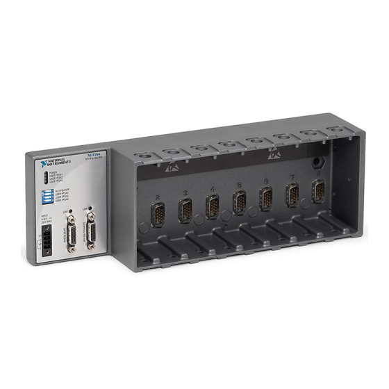
NI 9154
Reconfigurable Embedded Chassis with Integrated MXI-Express (x1)
This document describes the features of the NI 9154 and contains information about mounting
and operating the device.
Upstream
Connection
Downstream
Connection
NI 9154
Configuring the NI 9154
You can connect the NI 9154 to a MXI-Express host system and configure the powerup
options using a MXI-Express cable.
Connecting One or More NI 9154 Chassis to the MXI-
Express Host System or a Target
Complete the following steps to connect one or more NI 9154 chassis to a MXI-Express host
system or a target.
1.
Make sure the MXI-Express host system is set up and configured as described in the
MXI-Express (x1) Series User Manual.
2.
If the MXI-Express host system is powered up, power it down.
3.
If the NI 9154 is powered up, power it down.
MXI-Express
Switch
Hardware
Data
Xilinx
Virtex-5 LX50
Advertisement
Table of Contents

Related Manuals for National Instruments 9154


Summary of Contents for National Instruments 9154
- Page 1 Connecting One or More NI 9154 Chassis to the MXI- Express Host System or a Target Complete the following steps to connect one or more NI 9154 chassis to a MXI-Express host system or a target. Make sure the MXI-Express host system is set up and configured as described in the MXI-Express (x1) Series User Manual.
-
Page 2: Configuring Dip Switches
Use a MXI-Express (x1) cable to connect the MXI-Express host system to the Upstream port of the first NI 9154 in the chain. Use a MXI-Express (x1) cable to connect the Downstream port of the first NI 9154 to the Upstream port of the next NI 9154 in the chain. -
Page 3: Ports And Connectors
3. MXI Express Downstream Port Power Connector The NI 9154 has a power connector to which you can connect a primary and secondary power supply. The following table shows the pinout for the power connector. NI 9154 User Manual | © National Instruments | 3... - Page 4 If you apply power to both the V1 and V2 inputs, the NI 9154 operates from the V1 input. If the input voltage to V1 is insufficient, the NI 9154 operates from the V2 input.
- Page 5 9-30 V 25W MAX 1. CMOS Reset Button CMOS Reset Button The NI 9154 has a CMOS reset button that you can use to reset the CMOS and the BIOS. LEDs The NI 9154 provides the following LEDs. POWER USER FPGA1...
-
Page 6: Chassis Grounding Screw
35-mm DIN rail or a flat, metallic, vertical surface such as a panel or wall. You can mount the NI 9154 directly to the surface or use the NI Panel Mounting Kit. The following figure shows the NI 9154 mounted horizontally. Mounting the NI 9154 in other orientations or on a nonmetallic surface can reduce the maximum allowable ambient temperature and can affect the typical accuracy of modules in the NI 9154. - Page 7 Caution Make sure that no C Series modules are in the NI 9154 before mounting Dimensions The following figures show the front and side dimensions of the NI 9154. For detailed dimensional drawings and 3D models, visit ni.com/dimensions and search for the module number.
-
Page 8: Mounting Requirements
Mounting Requirements Your installation must meet the following requirements for cooling and cabling clearance. Allow 50.8 mm (2.00 in.) on the top and the bottom of the NI 9154 for air circulation, as shown in the following figure. Figure 5. NI 9154 Cooling Dimensions Cooling Outline 50.8 mm (2.00 in.) -
Page 9: Ambient Temperature
Measure the ambient temperature at each side of the NI 9154, 63.5 mm (2.50 in.) from the side and 50.8 mm (2.00 in.) forward from the rear of the NI 9154, as shown in the following figure. Figure 7. NI 9154 Ambient Temperature Location 63.5 mm... -
Page 10: Mounting The Device On A Panel
Align the NI 9154 and the DIN rail clip. Fasten the DIN rail kit to the NI 9154 using the screwdriver and M4x22 screws. NI provides these screws with the DIN rail mounting kit. Tighten the screws to a maximum torque of 1.3 N ·... -
Page 11: Panel Mounting Dimensions
Complete the following steps to mount the NI 9154 on a panel. Align the NI 9154 and the panel mounting plate. Fasten the panel mounting plate to the NI 9154 using the screwdriver and M4x22 screws. NI provides these screws with the panel mounting kit. Tighten the screws to a maximum torque of 1.3 N ·... -
Page 12: Mounting The Device Directly On A Flat Surface
• NI 9154 • M4 screw (x2), user provided, which must not exceed 8 mm of insertion into the NI 9154 What to Do Complete the following steps to mount the NI 9154 directly on a flat surface. NI 9154 Align the NI 9154 on the surface. -
Page 13: Worldwide Support And Services
United States, visit the Worldwide Offices section of ni.com/ niglobal to access the branch office websites, which provide up-to-date contact information, support phone numbers, email addresses, and current events. NI 9154 User Manual | © National Instruments | 13... - Page 14 CONTAINED HEREIN AND SHALL NOT BE LIABLE FOR ANY ERRORS. U.S. Government Customers: The data contained in this manual was developed at private expense and is subject to the applicable limited rights and restricted data rights as set forth in FAR 52.227-14, DFAR 252.227-7014, and DFAR 252.227-7015. © 2016 National Instruments. All rights reserved. 375840A-03 Apr16...
Need help?
Do you have a question about the 9154 and is the answer not in the manual?
Questions and answers