Table of Contents
Advertisement
Quick Links
OPERATING INSTRUCTIONS AND SPECIFICATIONS
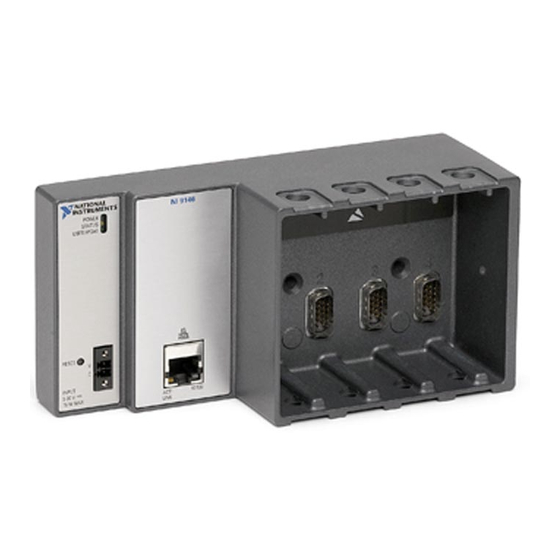
NI 9146
Ethernet Expansion Chassis for C Series Modules
N
N I
USER FPGA1
4
RESET
INPUT
9-30 V
15 W MAX
1 LEDs
2 RJ-45 Ethernet Port
This document describes how to connect the NI 9146 to a network and
how to use the features of the NI 9146. This document also contains
specifications for the NI 9146.
1
A
TIO
N
A
L
S
T U
R
M
EN S
T
POWER
POWER
STATUS
V
C
ACT/
LINK
3
3 Power Connector
4 Reset Button
Figure 1. NI 9146 Front Panel
NI 9146
10/100
2
Advertisement
Table of Contents

Related Manuals for National Instruments 9146


Summary of Contents for National Instruments 9146
- Page 1 4 Reset Button Figure 1. NI 9146 Front Panel This document describes how to connect the NI 9146 to a network and how to use the features of the NI 9146. This document also contains specifications for the NI 9146.
-
Page 2: Safety Guidelines
Operate the NI 9146 only as described in these operating instructions. Safety Guidelines for Hazardous Locations The NI 9146 is suitable for use in Class I, Division 2, Groups A, B, C, D, T4 hazardous locations; Class 1, Zone 2, AEx nC IIC T4 and Ex nL IIC T4 hazardous locations;... -
Page 3: Mounting The Chassis
Notes ni.com/info rdsoftwareversion which software you need to use the NI 9146. Mounting the Chassis You can mount the chassis horizontally on a flat, vertical, metallic surface such as a panel or wall. The maximum allowable ambient temperature for operation in this configuration is 70 °C. - Page 4 (1 in.) (1 in.) (7.01 in.) 4 mm (0.16 in.) 1 Measure ambient temperature here. 2 Chassis Grounding Screw Figure 3. NI 9146, Bottom View with Dimensions Note Go to and enter the Info Code to find the minimum ni.com/info rdcrioconn cabling clearance for C Series modules with other connector types.
- Page 5 You can use the NI 9904 panel mount kit to mount the NI 9146 on a flat surface. Complete the following steps. Fasten the chassis to the panel mount kit using a number 2 Phillips screwdriver and two M4 ×...
- Page 6 Figure 6. Installing the Panel Mount Accessory on the NI 9146 235.0 mm (9.25 in.) 215.9 mm (8.5 in.) 27.3 mm 29.5 mm (1.08 in.) (1.16 in.) 7.2 mm 9.5 mm (0.29 in.) (0.38 in.) NI 9146 EN S POWER...
- Page 7 Align the chassis on the surface. Fasten the chassis to the surface using M4 or number 8 flathead screws, as shown in Figure 8. National Instruments does not provide these screws with the chassis. NI 9146 EN S...
- Page 8 Figure 9. Installing the DIN Rail Clip on the NI 9146 Insert one edge of the DIN rail into the deeper opening of the DIN rail clip, as shown in Figure 10. 1 DIN Rail Clip 2 DIN Rail 3 DIN Rail Spring Figure 10.
- Page 9 I/O modules. Align the I/O module with an I/O module slot in the chassis as shown in Figure 12. The module slots are labeled 1 to 4, left to right. © National Instruments NI 9146 Operating Instructions and Specifications...
- Page 10 I/O modules. Squeeze the latches on both sides of the module and pull the module out of the chassis. NI 9146 Operating Instructions and Specifications ni.com...
- Page 11 Measurement & Automation Explorer (MAX). Installing software may change the network behavior of the chassis. For information Note about network behavior by installed software version, go to and enter the ni.com/info Info Code ipconfigcrio © National Instruments NI 9146 Operating Instructions and Specifications...
-
Page 12: Wiring Power To The Chassis
Ensure that the power supply is turned off. Caution Do not install or remove the power connector from the front panel of the NI 9146 while power is applied. Connect the positive lead of the power supply to the V terminal of the COMBICON power connector shipped with the NI 9146, and tighten the terminal screw. -
Page 13: Configuring Ip Settings
Configuring IP Settings When you power on the NI 9146 for the first time, it boots into safe mode because there is no software installed on it. This section describes how to configure the IP settings and install software on the chassis. -
Page 14: Understanding Led Indications
USER FPGA1 Figure 14. NI 9146 LEDs POWER LED The POWER LED is lit while the NI 9146 is powered on. This LED indicates that the power supply connected to the chassis is adequate. NI 9146 Operating Instructions and Specifications... - Page 15 Refer to LabVIEW Help for information about programming this LED. Troubleshooting Network Communication If the NI 9146 cannot communicate with the network, you can perform the following troubleshooting steps. Hold the Reset button down for about 5 s, until the Status LED lights yellow, then release the button.
-
Page 16: Where To Go From Here
Where to Go from Here Now that you have set up the NI 9146 and configured it on your network, you can start using it in your applications. The following figure shows the main components of the CompactRIO documentation that you may find helpful as you program and use the NI 9146. -
Page 17: Specifications
I/O modules you are using. Keep in mind that the resulting total power consumption is a maximum value and that the NI 9146 may require less power in your application. For more information about the I/O module power requirements, refer to the module operating instructions. -
Page 18: Physical Characteristics
To meet these specifications, you must panel mount the chassis and affix ferrules to the ends of the power terminal wires. Operating shock (IEC 60068-2-27) ........30 g, 11 ms half sine 50 g, 3 ms half sine, 18 shocks at 6 orientations NI 9146 Operating Instructions and Specifications ni.com... -
Page 19: Safety Voltages
EN 55011 (CISPR 11): Group 1, Class A emissions • AS/NZS CISPR 11: Group 1, Class A emissions • FCC 47 CFR Part 15B: Class A emissions • ICES-001: Class A emissions © National Instruments NI 9146 Operating Instructions and Specifications... -
Page 20: Online Product Certification
For more information about WEEE recycling centers, National Instruments WEEE initiatives, and compliance with WEEE Directive 2002/96/EC on Waste and Electronic Equipment, visit ni.com/environment/weee National Instruments (RoHS) National Instruments RoHS ni.com/environment/rohs_china (For information about China RoHS compliance, go to ni.com/environment/rohs_china NI 9146 Operating Instructions and Specifications ni.com... -
Page 21: Hazardous Locations
B, C, D, T4; Class 1, Zone 2, Ex nL IIC T4 Europe (DEMKO)........Ex nA nL IIC T4 Where to Go for Support The National Instruments Web site is your complete resource for technical support. At you have access to everything from ni.com/support troubleshooting and application development self-help resources to email and phone assistance from NI Application Engineers. - Page 22 For patents covering National Instruments products/technology, refer to the appropriate location: Help»Patents in your software, the patents.txt file on your media, or the National Instruments Patent Notice at ni.com/patents. You can find information about end-user license agreements (EULAs) and third-party legal notices in the NI-RIO Device Drivers Readme.
Need help?
Do you have a question about the 9146 and is the answer not in the manual?
Questions and answers