
Related Manuals for Gema Vertical axis ZA16


Summary of Contents for Gema Vertical axis ZA16
- Page 1 Rev. 00 1017 581 Operating instructions and Spare parts list Vertical axis ZA16 Translation of the original operating instructions...
- Page 2 To the best of our knowledge and belief, the information contained in this publication was correct and valid on the date of publication. Gema Switzerland GmbH makes no representations or warranties with respect to the contents or use of this publication, and reserves the right to revise this publication and make changes to its content without prior notice.
-
Page 3: Table Of Contents
Rev. 00 04/21 Table of contents About these instructions General information ....................7 Keeping the Manual ....................7 Safety symbols (pictograms) ................... 7 Presentation of the contents ................... 8 Figure references in the text ..............8 Safety Basic safety instructions ..................9 Product specific security regulations .............. - Page 4 Rev. 00 04/21 Reference point ..................28 Reference point and mechanical stops ..............28 Setting the reference point ..............28 Setting the lower mechanical stop ............29 Setting the upper mechanical stop ............30 Operation Decommissioning / Storage Introduction ......................33 Safety rules ....................
- Page 5 Rev. 00 04/21 ZA16 – complete ....................53 Toothed wheel....................... 54 Toothed wheel....................... 55 Z carriage ......................56 Drive unit (complete) ..................... 57 Proximity switch ....................58 Electrical module ....................59 Table of contents • 5 ZA16...
-
Page 7: About These Instructions
Please keep this Manual ready for later use or if there should be any queries. Safety symbols (pictograms) The following warnings with their meanings can be found in the Gema instructions. The general safety precautions must also be followed as well as the regulations in the relevant instructions. -
Page 8: Presentation Of The Contents
Rev. 00 04/21 ENVIRONMENT Indicates a potentially harmful situation which, if not avoided, may have harmful consequences for the environment. MANDATORY NOTE Information which must be observed. NOTICE Useful information, tips, etc. Presentation of the contents Figure references in the text Figure references are used as cross references in the descriptive text. -
Page 9: Safety
If this product is to be used for other purposes or other substances outside of our guidelines then Gema Switzerland GmbH should be consulted. -
Page 10: Special Safety Regulations
Unauthorized conversions and modifications can lead to injuries and damage to the equipment. The Gema Switzerland GmbH guarantee would no longer be valid. – Only original Gema spare parts should be used! The use of spare parts from other manufacturers will invalidate the Gema guarantee conditions! –... - Page 11 Rev. 00 04/21 WARNING Working without instructions Working without instructions or with individual pages from the instructions may result in damage to property and personal injury if relevant safety information is not observed. ► Before working with the device, organize the required documents and read the section "Safety regulations".
- Page 12 Rev. 00 04/21 12 • Safety ZA16...
-
Page 13: Transport
Rev. 00 04/21 Transport Introduction This chapter describes special precautions that must be taken during internal transport of the product if: – the customer himself must pack, transport and ship the product, such as to have renovations or service work carried out by the manufacturer –... - Page 14 Rev. 00 04/21 14 • Transport ZA16...
-
Page 15: Product Description
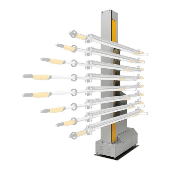
Rev. 00 04/21 Product description Intended use The ZA16 axis serves exclusively to move vertically powder applicators in automatic coating equipment. fig. 1 Observance of the operating, service and maintenance instructions specified by the manufacturer is also part of conformity of use. This product should only be used, maintained and started up by trained personnel, who are informed about and are familiar with the possible hazards involved. -
Page 16: Utilization
Rev. 00 04/21 Utilization The ZA16 type axis is used as the basis for all stages of automation, from a simple vertical stroke to complex, multi-dimensional processes. Depending on the design of the applicators, this unit may be used with all types of powder coating. -
Page 17: Schematic Presentation
Rev. 00 04/21 fig. 2: Structure Basement Z carriage Drive unit Power unit Toothed belt Holding brake U-axis bracket Schematic presentation fig. 3: Schematic presentation Axis control Motor cables Position regulator Drive motor Pulse generator wiring Product description • 17 ZA16... -
Page 18: Special Characteristics
Rev. 00 04/21 Special characteristics This axis is conspicuous because of its rugged construction, a new drive system and an improved Z axis carriage design. Further characteristics: – 130 kg load capacity for max. 8 gun axes type UA05 – Built-in holding brake –... -
Page 19: Cdb Position Regulator With Can Bus (Power Unit)
Rev. 00 04/21 CDB position regulator with CAN BUS (Power unit) fig. 5: CDB position regulator with CAN BUS X1 Load connections (Mains X4 RS 232 Interface voltage, Motor) X5 CAN addresses X2 Control connection X6 not occupied X3 Motor winding temperature X7 Pulse generator connection monitoring (optional) Product description •... -
Page 20: Technical Data
Rev. 00 04/21 Technical Data Versions The vertical axis is available, depending on operational area, in five versions with different standard stroke heights. ZA16- Reciprocator 2.385 m 2.885 m 3.385 m 3.885 m 4.385 m height – H Max. object 1.795 m 2.295 m 2.795 m... -
Page 21: Dimensions
Rev. 00 04/21 Dimensions fig. 6: Dimensions (in mm) A = 450 mm Lower reversing point B = 110 mm Min. vertical distance Sound pressure level ZA16 Normal operation < 60 dB(A) The sound pressure level was measured while the unit was in operation; measurements were taken at the most frequent operator positions and at a height of 1.7 m from the ground. -
Page 22: Rating Plate
Rev. 00 04/21 Rating plate fig. 7: Rating plate Fields with a gray background contain contract-specific data! 22 • Product description ZA16... -
Page 23: Assembly / Connection
Rev. 00 04/21 Assembly / Connection CAUTION Uncontrolled axis movement If a free-standing axis is not anchored firmly to the floor, uncontrolled movement of the machine or insufficient stability can cause injuries. ► Firmly anchor the axis to the floor with the supplied steel bolts if it is not mounted to another axis of motion. -
Page 24: Grounding Of The Axis
Rev. 00 04/21 Grounding of the axis DANGER Missing or incorrect grounding A bad or missing ground connection can be dangerous to the operator. ► Ground all metal parts of the axis according to the general, local safety regulations. ► Check regularly the grounding of the axis. At least one corresponding connection point at the axis is reserved for the potential equalization. -
Page 25: Electrical Connections / Cable Connections
Rev. 00 04/21 Electrical connections / cable connections fig. 9: Connections: CM40 control unit – vertical axis As an option, the connection 2.2 (24 V control) may be tied into a constant 24 VDC source so that in event of an interruption of power to the reciprocator the reference point remains in memory, i.e. - Page 26 Rev. 00 04/21 26 • Assembly / Connection ZA16...
-
Page 27: Start-Up
Rev. 00 04/21 Start-up Preparation for start-up ATTENTION Incorrect setting of the upper and lower stroke limits will cause damages to the reciprocator, to the booth or to the applicators! ► Before connecting or switching on the reciprocator, read carefully these operating instructions! ►... -
Page 28: Reference Point
Rev. 00 04/21 Reference point At every start-up after the mains have been interrupted, the reference point of the axis must be referred again (see "Reference point and mechanical stops"). After the reference point is reached, the axis begins to carry out the movements set on the axis control unit. Before the reciprocator is put into operation, the upper stroke limit must be set on the reciprocator control unit (see therefore the corresponding reciprocator control unit operating manual)! -
Page 29: Setting The Lower Mechanical Stop
► Fit the mechanical stop to the gun slots because the axis moves up to 25 mm below the control’s zero point, when referencing! The position of the upper and the lower stop plate is set by a Gema service engineer when the reciprocator is assembled. -
Page 30: Setting The Upper Mechanical Stop
Rev. 00 04/21 Remove the boarding/side panels Loosen the screws and move the lower stop plate up to the Z carriage Tighten the screws Tightening torque: 55 Nm Refit the boarding/side panels Setting the upper mechanical stop The setting of the upper mechanical stop must take place without load and the reciprocator must be disconnected from mains! In order to set the upper mechanical stop, the stop position hast to be measured –... -
Page 31: Operation
Rev. 00 04/21 Operation The axis is operated exclusively by the CMxx control unit. See chapter "Technical Data" on page 20. fig. 11: MagicControl CM40 axis control unit The axis control unit permits the selection and the start/stop of the travel programs by the operator on the panel. - Page 32 Rev. 00 04/21 32 • Operation ZA16...
-
Page 33: Decommissioning / Storage
Rev. 00 04/21 Decommissioning / Storage Introduction Safety rules Before lifting a reciprocator off of its horizontal axes, it must be secured from falling over with a lifting device such as a crane, fork lift, etc. The point of attachment is the eye bolt (D) at the top of the reciprocator. fig. -
Page 34: Type Of Storage
Rev. 00 04/21 Type of storage For safety reasons, reciprocators should only be stored in a horizontal position. fig. 13 Storage duration If the physical conditions are maintained, the unit can be stored indefinitely. Space requirements The space requirements correspond to the sizes of the axes of motion. The load-bearing capacity of the floor should be at least 200 kg/m². -
Page 35: Maintenance During Storage
Rev. 00 04/21 Maintenance during storage Maintenance schedule No maintenance schedule is necessary. Maintenance works During long-term storage, periodically perform a visual check for corrosion. Decommissioning / Storage • 35 ZA16... - Page 36 Rev. 00 04/21 36 • Decommissioning / Storage ZA16...
-
Page 37: Maintenance / Repairs
Rev. 00 04/21 Maintenance / Repairs General information WARNING Before start-up works are done, make certain that nobody can switch on the axis! ► Switch off and lock the mains switch! ► The axis has to be free of load! WARNING Injuries can occur inside the protective fence due to the movement of the axis! -
Page 38: Maintenance Schedule
Rev. 00 04/21 Maintenance schedule The following components or modules are subject to a maintenance schedule: Component Activity Tool Interval – Check for unusual noises 1 x weekly Air guns Check for powder residues Side walls 1 x weekly and clean Soft cloth –... -
Page 39: Replacing The Drive Unit
Rev. 00 04/21 Replacing the drive unit Caution! Risk of burns There is the risk of burns if contact is made with electrical components that have become overheated! ► All work must be carried out only by trained personnel and when no power is applied! If it is necessary to replace a drive unit gearbox, the complete motor unit must be dismantled from the reciprocator base. -
Page 40: Toothed Belt
Rev. 00 04/21 – The individual parts can now be removed and replaced 11. Loosen 4 flange bolts and remove the defective motor-gearbox unit 12. Loosen the grub screw and pull the coupling half off the motor shaft 13. Install new motor-gearbox unit The installation takes place exactly in the reverse order! ATTENTION Incorrectly assembled parts may cause malfunctions or defects... -
Page 41: Replacing The Toothed Belt
Rev. 00 04/21 For safety reasons, two people should always carry out the following maintenance work! Replacing the toothed belt Procedure: Switch off the power supply. Release the motor brake manually, let the Z carriage move down onto the lower stop Remove lateral covers Remove the locking plates (A) and loosen the tensioning screws (B), so that the toothed belt is slack... -
Page 42: Adjusting The Toothed Belt Tension With The Belt Tension Measuring Device
Rev. 00 04/21 Adjust the toothed belt tension so that the toothed belt is fully seated in both directions Fig. 16: Adjusting the toothed belt tension with the belt tension measuring device Preferably the belt tension meter Type Belt Tension Pro should be used for this tension procedure. -
Page 43: Toothed Wheel
Rev. 00 04/21 – The natural frequency generated in this way is detected by the measuring device. The voltage is calculated from the measured data. Turn the clamping screws (B) evenly until the required toothed belt tension is reached: 1900 – 2000 N Without loading the Z-carriage 1950 –... - Page 44 Rev. 00 04/21 Remove the toothed belt from the toothed wheel Remove the toothed wheel and replace it The installation takes place exactly in the reverse order! – If necessary, remove the service cover on the base, to check if the toothed belt is sitting correctly on the toothed drive wheel –...
-
Page 45: Rollers - Z Carriage
Rev. 00 04/21 Rollers – Z carriage If the Z carriage starts to vibrate excessively during operation, especially at the reversing points, in most cases the cause lies in too much play in the carriage rollers, or even loose rollers! fig. -
Page 46: Maintenance Of The Position Regulator
Rev. 00 04/21 Maintenance of the position regulator The position regulator does not require a preventive maintenance. However, it is recommended to carry out the following inspections by the user in regular intervals: – Check condition and tightness of the cable connections. Replacing the position regulator If a position regulator exchange was made, it is to be noted, that all shielded cables are properly attached again! -
Page 47: Fault Clearance
Rev. 00 04/21 Fault clearance ATTENTION Malfunctions may be fixed by trained personnel only! Error messages on the axis control or on the position regulator are also to be observed! Fault Cause Corrective action The Z carriage does Z carriage check the load not move overloaded... - Page 48 Rev. 00 04/21 Fault Cause Corrective action Squeaking noise toothed belt rides up check the toothed during operation on the flanged wheel belt, tension correctly, if necessary The Z carriage runs pulse generator replace the pulse into the lower stroke defective generator limit or into the lower...
-
Page 49: Disposal
Requirements on personnel carrying out the work The disposal of the product is to be carried out by the owner or operator. When disposing of components that are not manufactured by Gema, the instructions in the respective third-party manufacturer’s documentation must be observed. -
Page 50: Materials
Rev. 00 04/21 Materials The materials must be sorted according to material groups and taken to the appropriate collection points. Disposal of operating material The operating material is very harmful to the environment if it is improperly disposed of. Therefore, the instructions and information contained in the safety data sheets must be adhered to when disposing of the operating material. -
Page 51: Spare Parts List
When using the spare parts from other manufacturers the explosion protection is no longer guaranteed. If any damage is caused by this use all warrantee claims become invalid! ► Only original Gema spare parts should be used! Spare parts list • 51 ZA16... -
Page 52: Za16 - Complete
Rev. 00 04/21 ZA16 – complete Drive unit – complete, see also "Drive unit (complete)" Hexagon screw – M6x12 mm 1005 774 Cable lead-through – Ø 50 mm, 5+4 1004 006 Electrical module, see "Electrical module" Z carriage – complete, see "Z carriage" Toothed wheel, see "Toothed wheel"... -
Page 53: Za16 - Complete
Rev. 00 04/21 ZA16 – complete fig. 19: ZA16 – complete Spare parts list • 53 ZA16... -
Page 54: Toothed Wheel
Rev. 00 04/21 Toothed wheel Eye bolt – M16 264 415 Guide plate 1019 229 Hexagon shakeproof nut – M8 244 449 Hexagon ribbed nut – M10 234 656 Counter profile – 40/20x115 mm 386 774 Toothed wheel 1020 717 Toothed belt 1019 225#* ZA16-13 –... -
Page 55: Toothed Wheel
Rev. 00 04/21 Toothed wheel fig. 20: Toothed wheel Spare parts list • 55 ZA16... -
Page 56: Z Carriage
Rev. 00 04/21 Z carriage Carriage – fixed side (without pos. 9, 10) order specific Carriage – removable side (without pos. 9, 10) order specific Roller – complete 307 165# Spacer sleeve 308 013 Hexagon screw – M10x110 mm 214 221 Hexagon screw –... -
Page 57: Drive Unit (Complete)
Rev. 00 04/21 Drive unit (complete) Motor/gearbox unit – 1.5 kW, complete 1022 545 Pulse generator 268 925 Coupling – complete (incl. pos 4 and 5) 1022 544 Feather key – 8x7x32 mm 1022 548 Grub screw – M8x20 mm 1022 549 Drive shaft 1022 541... -
Page 58: Proximity Switch
Rev. 00 04/21 Proximity switch Hexagon screw – M10x180 mm 201 855 Stop plate 1022 575 Rubber buffer – Ø 35x40 mm, M8 211 664 Counter profile – 40/20x115 mm 386 774 Limit switch holder 1022 576 Hexagon ribbed nut – M10 234 656 Proximity switch 1017 650... -
Page 59: Electrical Module
Rev. 00 04/21 Electrical module For all electric components, see also the Spare parts list in the enclosed wiring diagram! Position regulator CDB (please indicate the axis serial number – see Rating plate) 1022 553 CAN bus cable 1022 650 Adhesive seal strip 103 357* Grip... - Page 61 Rev. 00 04/21 Index About these instructions ........7 Operation ............31 Assembly ............23 Pictograms ............7 Basic safety instructions ........9 Presentation of the contents ......8 Belt tension meter ..........42 Product description .......... 15 Product specific security regulations ....9 Connection ............
- Page 62 Rev. 00...
Need help?
Do you have a question about the Vertical axis ZA16 and is the answer not in the manual?
Questions and answers