EVGA X79 DARK User Manual
Hide thumbs
Also See for EVGA X79 DARK:
- Key specs (2 pages) ,
- User manual (35 pages) ,
- Visual manual (2 pages)
Table of Contents
Advertisement
Advertisement
Table of Contents

Related Manuals for EVGA EVGA X79 DARK


Summary of Contents for EVGA EVGA X79 DARK
- Page 1 User Guide EVGA X79 DARK Motherboard...
-
Page 2: Table Of Contents
Table of Contents Before You Begin… ........................4 Parts NOT in the Kit ........................5 Intentions of the Kit ........................5 Motherboard Specifications ..................... 6- Unpacking and Parts Descriptions ....................8 Equipment........................... 8-9 Hardware Installation ........................10 Safety Instructions ........................10 Intel X79 Chipset Motherboard………...…………………………………………………11-13 Preparing the Motherboard ..................... - Page 3 Clear CMOS Button ........................25 RESET and POWER Button ....................25 Post Port Debug LED and LED Status Indicators ...............26 Installing Drivers and Software ....................27 Windows 7/Vista/XP Driver Installation ................27 POST Codes ........................... 28-31 EVGA Glossary of Terms ....................32-34 Compliance Information ......................35...
-
Page 4: Before You Begin
Also, with built in EVGA EVBot support*, you can overclock on the fly from the palm of your hand. Uncompromised Features – This board is loaded with the latest technologies like a full UEFI BIOS, USB 3.0 Ports, SATA III/6G support, PCI-E 3.0 ports, E-SATA, a... -
Page 5: Parts Not In The Kit
PCI Express Graphics Card Power Supply EVGA assumes you have purchased all the necessary parts needed to allow for proper system functionality. For a full list of supported CPUs on this motherboard, please visit www.evga.com/support/motherboard Intentions of the Kit This kit provides you with the motherboard and all connecting cables necessary to install the motherboard into a PC case. -
Page 6: Motherboard Specifications
EVGA X79 Motherboard Motherboard Specifications Size: EATX form factor of 12 inches x 10.3 inches Microprocessor support: Intel Socket 2011 Processor Operating systems: Supports Windows 8 / 7 / Vista / XP Contains Intel X79 chipset: ... - Page 7 SATA Ports: Intel X79 PCH Controller 4x SATA 2 Ports up to 3G (300 MB/s) data transfer rate 2x SATA 3 Ports up to 6G (600 MB/s) data transfer rate - Support for RAID 0, RAID 1, RAID 0+1, RAID 5, AND RAID 10 *If 6G ports are used in the same array as 3G ports, the SATA 3 6G ports will adjust down to SATA 2 3G speeds.
-
Page 8: Unpacking And Parts Descriptions
Unpacking and Parts Descriptions Equipment The following accessories are included with the EVGA X79 Dark Motherboard: The EVGA X79 Dark Motherboard This PCI-E motherboard contains the Intel X79 chipset and is ® -ready. Visual Guide Helps to quickly and visually guide you through the hardware installation of the motherboard. - Page 9 2-Port USB 3.0 Bracket Allows addition of 2 USB 3.0 ports by Connecting to the motherboard header. SATA 3G/6G Data Cables Used to support the SATA protocol and each one connects a single drive to the motherboard. ® 4-way SLI Bridge Bridges four graphics cards together which allows for ®...
-
Page 10: Hardware Installation
Hardware Installation This section will guide you through the installation of the motherboard. The topics covered in this section are: Preparing the motherboard Installing the CPU Installing the Cooling Device Installing the memory Installing the motherboard Connecting cables ... -
Page 11: Intel X79 Chipset Motherboard
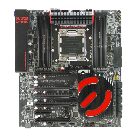
Intel X79 Chipset Motherboard The EVGA X79 Dark Motherboard with the Intel X79 and PCH Chipset is a SLI-ready motherboard. Figure 1 shows the motherboard and Figure 2 shows the back panel connectors FIGURE 1. X79 Dark Motherboard Layout... - Page 12 1. CPU Socket 2011 13. Debug LED 25. PCI-E Slot 4x 2. Intel X79 Southbridge 14. USB 2.0 Headers 26. Front Panel Audio Connector 3. CPU Fan Header 15. USB 3.0 Headers 27. S/PDIF Out 4. DDR3 Memory DIMM Slots 1-8 16.
- Page 13 Figure 2. Chassis Rear Panel Connectors 1. Bluetooth 4. CMOS Reset Switch 7. eSata Ports 2. USB 2.0 5. Optical S/DIF Out 8. NIC 3. USB 3.0 6. EVBot Connecter 9. Analog Audio Output Jacks 2/2.1 Analog Audio Port Breakdown Channel 4.0/4.1 Channel 5.1 (6 Channel)
-
Page 14: Preparing The Motherboard
Preparing the Motherboard Installing the CPU Be very careful when handling the CPU. Hold the processor only by the edges and do not touch the bottom of the processor. Use the following procedure to install the CPU onto the motherboard: Unhook the left socket lever by pushing down ... -
Page 15: Installing The Cooling Device
Align the notches on the CPU to the notches in the socket. Lower the processor straight down into the socket. Note: Make sure the CPU is fully seated and level in the socket. Lower the load plate so it is resting on the CPU. ... -
Page 16: Installing System Memory (Dimms)
Installing System Memory (DIMMs) Your new motherboard has eight 240-pin slots for DDR3 memory. These slots support 2GB, 4GB and 8GB DDR3 DIMMs. There must be at least one memory slot populated to ensure normal operation. The Intel X79 chipset supports quad channel memory;... -
Page 17: Installing The I/O Shield
working with an empty system case. Determine if it would be easier to make all the connections prior to this step or to secure the motherboard and then make all the connections. It is normally easier to secure the motherboard first. Use the following procedure to install the I/O shield and secure the motherboard into the chassis. -
Page 18: Securing The Motherboard Into A System Case
Securing the Motherboard into a System Case Most system cases have a base with mounting holes you thread standoffs onto to allow the motherboard to be secured to the chassis and help to prevent short circuits. If there are studs that do not align with a mounting hole on the motherboard, it is recommended that you remove that standoff to prevent the possibility of a short circuit. -
Page 19: 24Pin Atx Power (Pw1)
24pin ATX Power (PW1) is the main power supply connector located along the right edge of the board. Make sure that the power supply cable and pins are properly aligned with the connector on the motherboard. Firmly plug the power supply cable into the connector and make sure it is secure. -
Page 20: 8Pin Atx 12V Power
8-pin ATX 12V Power ( PW12-1 & PW12-2 , the 8-pin ATX 12V power connections, are used to PW12-1 & PW12-2 provide power to the CPU. Align the pins to the connector and press firmly until seated. The secondary is optional for improved overclocking. +12V BIOS Select Switch The BIOS Select Switch is located directly on the bottom edge of the... -
Page 21: Usb Headers
LED indicates the system’s status. When the system is powered on, the LED will be on. Note: Some system cases may not have all four cables. Be sure to match the name on the connectors to the corresponding pins. Signal PWRSW ... - Page 22 Secure the bracket to either the front or rear panel of your chassis (not all chassis are equipped with the front panel option). Connect the two ends of the cables to the USB 2.0 or 3.0 headers on the motherboard. Connector Signal 5V_DUAL...
-
Page 23: Audio
Audio The audio connector supports HD audio standard and provides two kinds of audio output choices: the Front Audio and the Rear Audio. Connector Signal PORT1_L Front Audio Connector AUD_GND PORT1_R PRECENCE_J PORT2_R SENSE1_RETURN SENSE_SEND Empty PORT2_L SENSE2_RETURN... -
Page 24: Pci-E X1 Slots
PCI-E x4 Slot There are PCI-E x4 slots that are designed to accommodate less bandwidth- intensive cards, such as a sound or network card. PCI-E x16/x8 Slots These PCI-E slots are reserved for Graphics Cards and PCI-E x1, x4, x8 and x16 devices. -
Page 25: Onboard Buttons
Onboard Buttons These onboard buttons include RESET, POWER and Clear CMOS. These functions allow you to easily reset the system, turn on/off the system, or clear the CMOS. Clear CMOS Button The motherboard uses the CMOS RAM to store all the set parameters. The CMOS can be cleared by pressing the Clear CMOS button either onboard or on the external I/O Panel. -
Page 26: Post Port Debug Led And Led Status Indicators
Post Debug LED and LED Status Indicators Post Port Debug LED Provides two-digit POST codes to show why the system may be failing to boot. It is useful during troubleshooting situations. This Debug LED will also display current CPU socket temperatures after the system has fully booted into the Operating System. -
Page 27: Installing Drivers And Software
32bit and 64bit versions of Windows 8, 7, Vista and XP. The kit comes with a CD that contains utilities, drivers, and additional software. The CD that has been shipped with the EVGA X79 Motherboard contains the following software and drivers: Chipset Drivers ... -
Page 28: Post Codes
POST Codes This section provides the AMI POST Codes for the EVGA X79 Dark Motherboard during system boot The POST Codes are displayed on the Debug LED readout located directly onboard the motherboard. Debug LED with CPU Temperature Monitor This Debug LED will also display current CPU temperatures after the system has fully booted into the Operating System. - Page 29 Memory initialization. Programming memory timing information Memory initialization. Configuring memory Memory initialization (other). Reserved for ASL (see ASL Status Codes section below) Memory Installed CPU post-memory initialization is started CPU post-memory initialization. Cache initialization CPU post-memory initialization. Application Processor(s) (AP) initialization CPU post-memory initialization.
- Page 30 EC-EF Reserved for future AMI error codes Recovery condition triggered by firmware (Auto recovery) Recovery condition triggered by user (Forced recovery) Recovery process started Recovery firmware image is found Recovery firmware image is loaded F5-F7 Reserved for future AMI progress codes Recovery PPI is not available Recovery capsule is not found Invalid recovery capsule...
- Page 31 USB Reset USB Detect USB Enable 9E–9F Reserved for future AMI codes IDE initialization is started IDE Reset IDE Detect IDE Enable SCSI initialization is started SCSI Reset SCSI Detect SCSI Enable Setup Verifying Password Start of Setup Reserved for ASL (see ASL Status Codes section below) Setup Input Wait Reserved for ASL (see ASL Status Codes section...
-
Page 32: Evga Glossary Of Terms
Error loading Boot Option (LoadImage returned error) Boot Option is failed (StartImage returned error) EVGA Glossary of Terms AC – Alternating Current ACPI - Advanced Configuration and Power Interface AFR – Alternate Frame Rendering APIC - Advanced Programmable Interrupt Controller ACPI –... - Page 33 HDMI - High-Definition Multimedia Interface HDR – High Dynamic Range Lighting HPET - High Precision Event Timer HT – Hyper-Threading HSF - Heat Sink Fan I/O - Input/ Output IEEE - Institute of Electrical and Electronics Engineers IGP - Integrated Graphics Processors IMC –...
- Page 34 PLL – Phase Locked Loop POST – Power on Self Test PWM – Pulse Width Modulation QDR - Quad Data Rate QPI – Quick Path Interconnect RAID - Redundant Array of Inexpensive Disks RAM – Random Access Memory ROM – Read Only Memory RGB - Red Green Blue SATA - Serial Advanced Technology Attachment SAS –...
-
Page 35: Compliance Information
Original Purchaser. Upon termination, for any reason, all copies of Software and materials must be immediately returned to EVGA and the Original Purchaser shall be liable to EVGA.com CORP for any and all damages suffered as a result of the violation or default.
Need help?
Do you have a question about the EVGA X79 DARK and is the answer not in the manual?
Questions and answers