Table of Contents
Advertisement
Quick Links
Advertisement
Table of Contents

Related Manuals for CommScope ValuLine VHLP 3 Series


Summary of Contents for CommScope ValuLine VHLP 3 Series
-
Page 2: Installation Instructions
Aviso: CommScope no acepta ninguna obligación ni responsabilidad como resultado de prácticas incorrectas o peligrosas de instalación, inspección, mantenimiento o retiro. Avis : CommScope décline toute responsabilité pour les conséquences de procédures d’installation, d’inspection, d’entretien ou de retrait incorrectes ou dangereuses. -
Page 3: Section 1 Contents & Introduction
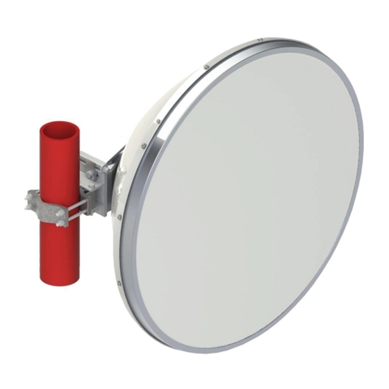
INTRODUCTION This instruction describes how to unpack and adjust a factory assembled VHLP(X)3 antenna. Mount to the left of the supporting structure. It can also be configured to mount to right - refer to full antenna assembly instructions on CommScope.com... - Page 4 INSTALLATION SECTION 2 7835437 INSTRUCTIONS SAFETY INSTRUCTIONS Page 4 of 14...
- Page 5 INSTALLATION SECTION 2 7835437 INSTRUCTIONS SAFETY INSTRUCTIONS Page 5 of 14...
- Page 6 INSTALLATION SECTION 2 7835437 INSTRUCTIONS SAFETY INSTRUCTIONS Page 6 of 14...
-
Page 7: Section 3 Equipment And Tools
INSTALLATION SECTION 3 7835437 INSTRUCTIONS EQUIPMENT AND TOOLS Page 7 of 14 Table 1 Supplied Equipment Item Description Assembled antenna Integration Unit * 1 or 2 Flange Hardware Kit * *Either Item B (Integration Unit) or Item C (Flange Hardware Kit) are supplied. Tools TOOL REQUIREMENTS Thread Diameter in MM... - Page 8 INSTALLATION SECTION 4 7835437 INSTRUCTIONS UNPACKING Page 8 of 14 Unpacking Handle antenna CAREFULLY at all times Non-integrated antennas supplied flange hardware kit this will vary dependent on antenna model OEM direct mount radio integration (certain models only). Non-integrated antennas have factory feed fitted flange outputs.
- Page 9 INSTALLATION SECTION 4 7835437 INSTRUCTIONS Page 9 of 14 UNPACKING Do not discard these parts Carefully lay antenna on clear, flat ground. Then remove brace Do not apply excessive weight to antenna assembly. Non-integrated antennas have factory feed fitted flange outputs this will vary dependent on antenna model...
- Page 10 INSTALLATION SECTION 5 7835437 INSTRUCTIONS MOUNT ATTACHMENT AND ALIGNMENT Page 10 of 14 Where required, fit radio integration unit at this stage - refer to instructions supplied with integration unit. galv 38Nm 5% SLING 90-120mm Pole Secure assembled mount to pole ensuring clamp bolts are seated correctly.
- Page 11 INSTALLATION SECTION 5 7835437 INSTRUCTIONS MOUNT ATTACHMENT AND ALIGNMENT Page 11 of 14 Loosen screws G1 Loosen screws G2 Pan Left Pan Right Azimuth adjustment Adjust eyebolt. On completion tighten screws G1 to 50Nm ± 5% and screw G2 to 38Nm ± 5% Adjustment Range ±15°...
- Page 12 INSTALLATION SECTION 5 7835437 INSTRUCTIONS Page 12 of 14 MOUNT ATTACHMENT AND ALIGNMENT Antenna Offset Left Antenna Offset Right Refer to full antenna assembly instructions on www.commscope.com for details on how to switch mount offset...
- Page 13 INSTALLATION SECTION 6 7835437 INSTRUCTIONS TRANSITION POLARISATION ADJUSTMENT Page 13 of 14 Single polarisation Step 1 Remove blanking plate, screws, washers o-ring (gasket) Vertical polarisation transition Step 2 Flat provided to aid Step 3 fine polarisation adjustment Loose screws a turn to allow After fine adjustment, tighten Horizontal polarisation transition to rotate...
-
Page 14: Section 7 General Information
INSTALLATION SECTION 7 7835437 INSTRUCTIONS GENERAL INFORMATION Page 14 of 14 7 General Information 7.1 General maintenance The antenna is designed such that minimal maintenance is required. Other than strong wind conditions the unit is not subject to abnormal forces and regular inspection and maintenance should ensure trouble free operation.
Need help?
Do you have a question about the ValuLine VHLP 3 Series and is the answer not in the manual?
Questions and answers