Table of Contents
Advertisement
Quick Links
Advertisement
Table of Contents

Related Manuals for HIKVISION DS-KD7003EY-IME2


Summary of Contents for HIKVISION DS-KD7003EY-IME2
- Page 1 DS-KD7003EY-IME2 Module Door Station User Manual...
- Page 2 ● Products described in this Document, which may include licenses obtained from third parties. Any part of the Document, including text, pictures, graphics, etc., belongs to Hikvision. No part ● of this Document may be excerpted, copied, translated, or modified in whole or in part by any means without written permission.
- Page 3 DS-KD7003EY-IME2 Module Door Station User Manual PRODUCT, EVEN IF HIKVISION HAS BEEN ADVISED OF THE POSSIBILITY OF SUCH DAMAGES OR LOSS. YOU ACKNOWLEDGE THAT THE NATURE OF THE INTERNET PROVIDES FOR INHERENT SECURITY ● RISKS, AND HIKVISION SHALL NOT TAKE ANY RESPONSIBILITIES FOR ABNORMAL OPERATION, PRIVACY LEAKAGE OR OTHER DAMAGES RESULTING FROM CYBER-ATTACK, HACKER ATTACK, VIRUS INFECTION, OR OTHER INTERNET SECURITY RISKS;...
- Page 4 DS-KD7003EY-IME2 Module Door Station User Manual Symbol Conventions The symbols that may be found in this document are defined as follows. Symbol Description Indicates a hazardous situation which, if not avoided, will or could Danger result in death or serious injury.
- Page 5 DS-KD7003EY-IME2 Module Door Station User Manual Regulatory Information EU Conformity Statement This product and - if applicable - the supplied accessories too are marked with "CE" and comply therefore with the applicable harmonized European standards listed under the EMC Directive 2014/30/EU, the RoHS Directive 2011/65/EU 2012/19/EU (WEEE directive): Products marked with this symbol cannot be disposed of as unsorted municipal waste in the European Union.
- Page 6 DS-KD7003EY-IME2 Module Door Station User Manual Conformément à la réglementation d'Industrie Canada, le présent émetteur radio peut fonctionner avec une antenne d'un type et d'un gain maximal (ou inférieur) approuvé pour l'émetteur par Industrie Canada. Dans le but de réduire les risques de brouillage radioélectrique à l'intention des autres utilisateurs, il faut choisir le type d'antenne et son gain de sorte que la puissance isotrope rayonnée équivalente (p.i.r.e.) ne dépasse pas l'intensité...
- Page 7 DS-KD7003EY-IME2 Module Door Station User Manual About this Manual Get the manual and related software from or the official website (http://www.hikvision.com). Product Model Door Station DS-KD7003EY-IME2 Scan the QR code to get the User Manual for detailed information.
-
Page 8: Table Of Contents
DS-KD7003EY-IME2 Module Door Station User Manual Contents Chapter 1 Appearance ........................ 1 Chapter 2 Terminal and Wiring ....................3 2.1 Terminal Description ......................3 Chapter 3 Installation ......................... 5 3.1 One-Module Installation ......................6 3.1.1 One-Module Surface Mounting ..................6 3.1.2 One-Module Flush Mounting .................. - Page 9 DS-KD7003EY-IME2 Module Door Station User Manual 12.2 Forget Password via PC Web ....................58 Chapter 13 Overview ........................ 59 13.1 Overview on Mobile Web ....................59 13.2 Overview on PC Web ......................59 Chapter 14 Person Management ....................61 14.1 Person Management on Mobile Web ................61 14.2 Person Management on PC Web ..................
- Page 10 DS-KD7003EY-IME2 Module Door Station User Manual 20.2 Set Motion Detection on PC Web ..................73 Chapter 21 Access Control Settings ................... 74 21.1 Set Door Parameters on Mobile Web ................74 21.2 Set Public Password on Mobile Web .................. 74 21.3 Set I/O Parameters on Mobile Web ...................
- Page 11 DS-KD7003EY-IME2 Module Door Station User Manual Chapter 29 Device Debugging on PC Web ................. 89 Chapter 30 View Online Document ................... 90 30.1 View Online Document on Mobile Web ................90 30.2 View Online Document on PC Web ..................90 Chapter 31 View Open Source Software License ...............
-
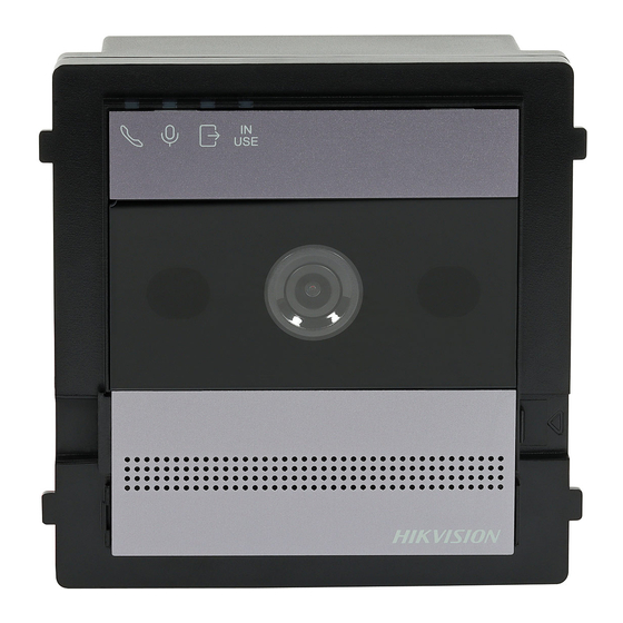
Page 12: Chapter 1 Appearance
DS-KD7003EY-IME2 Module Door Station User Manual Chapter 1 Appearance Main Unit Figure 1-1 Main Unit Appearance Note Loudspeaker/Mic Adjustment Area: Press the buckle and push the tag to the left to uncover the ● metal cover. Remove the dust-proof plug and use drill to adjust the volume of loudspeaker and the microphone. - Page 13 DS-KD7003EY-IME2 Module Door Station User Manual 10 s to synchronize the device parameters to the web, including contacts, language, device time, etc. Name tag 2: one call button Press once to call a specific room No. Name tag 3: No call button...
-
Page 14: Chapter 2 Terminal And Wiring
DS-KD7003EY-IME2 Module Door Station User Manual Chapter 2 Terminal and Wiring 2.1 Terminal Description Terminals Figure 2-1 Main Unit Terminals Table 2-1 Descriptions of Terminals and Interfaces Interface Description 485- Module- c onnecting Interface 485+ 12V 1A Door Lock Relay Output (NC) - Page 15 DS-KD7003EY-IME2 Module Door Station User Manual Interface Description Grounding AIN1 Alarm In Interface AIN2 Alarm In Interface 2-WIRE Interface 2-Wire Interface Wiring Figure 2-2 Wiring of Door Station...
-
Page 16: Chapter 3 Installation
DS-KD7003EY-IME2 Module Door Station User Manual Chapter 3 Installation Note Make sure the device in the package is in good condition and all the assembly parts are included. ● Sub module must work along with the main unit. ● Set the sub module address before start the installation steps. -
Page 17: One-Module Installation
DS-KD7003EY-IME2 Module Door Station User Manual 3.1 One-Module Installation 3.1.1 One-Module Surface Mounting Before You Start Figure 3-1 Mounting Frame Note The depth of one module mounting frame is 33 mm. ● The dimensions above are for reference only. The actual size can be slightly different from the ●... - Page 18 DS-KD7003EY-IME2 Module Door Station User Manual Figure 3-2 Drill Screw Holes 3. Remove the sticker and insert the expansion sleeves into the screw holes. 4. Fix the mounting frame onto the wall with 4 expansion bolts.
- Page 19 DS-KD7003EY-IME2 Module Door Station User Manual Figure 3-3 Fix the Mounting Frame 5. Connect the cables to the corresponding interfaces of the main unit and insert the main unit into the frame.
- Page 20 DS-KD7003EY-IME2 Module Door Station User Manual Figure 3-4 Insert the Main Unit 6. Fix the cover onto the frame.
-
Page 21: One-Module Flush Mounting
DS-KD7003EY-IME2 Module Door Station User Manual Figure 3-5 Fix the Cover 3.1.2 One-Module Flush Mounting Before You Start Steps 1. Drill an installation hole, and pull the cables out. Note The suggested dimension of installation hole is 33 mm (depth). - Page 22 DS-KD7003EY-IME2 Module Door Station User Manual Figure 3-6 Drill Installation Hole 2. Remove the plastic sheet of the cable entry. 3. Mark the mounting frame screw holes on the wall. 1) Route the cables through the mounting frame hole. 2) Insert the mounting frame into the installation hole.
- Page 23 DS-KD7003EY-IME2 Module Door Station User Manual Figure 3-7 Mark the Screw Holes 4. Drill 4 holes according to marks on the wall, and insert the expansion sleeves into the screw holes. 5. Route the cables through the gang box hole. Insert the mounting frame into the installation...
- Page 24 DS-KD7003EY-IME2 Module Door Station User Manual Figure 3-8 Fix the Mounting Fame 6. Fill the gap between the mounting frame and the wall with concrete. Remove the 4 mounting ears with tool after concrete is dry.
- Page 25 DS-KD7003EY-IME2 Module Door Station User Manual Figure 3-9 Remove the Mounting Ears 7. Connect the cables to the corresponding interfaces of the main unit and insert the unit into the mounting frame.
- Page 26 DS-KD7003EY-IME2 Module Door Station User Manual Figure 3-10 Insert the Main Unit 8. Fix the cover and the main unit with 2 socket head cap screws by using a hexagon wrench (supplied).
- Page 27 DS-KD7003EY-IME2 Module Door Station User Manual Figure 3-11 Fix the Cover...
-
Page 28: Two-Module Installation
DS-KD7003EY-IME2 Module Door Station User Manual 3.2 Two-Module Installation 3.2.1 Two-Module Surface Mounting Before You Start Figure 3-12 Mounting Frame... - Page 29 DS-KD7003EY-IME2 Module Door Station User Manual Note The suggested depth of the installation hole is 33 mm. ● The dimensions above are for reference only. The actual size can be slightly different from the ● theoretical dimension. Steps 1. Paste the installation Sticker 1 onto the wall. Make sure the sticker is placed horizontally via measuring with the gradienter.
- Page 30 DS-KD7003EY-IME2 Module Door Station User Manual Figure 3-14 Fix the Mounting Frame 5. Thread the module-connecting line across the thread hole of the frame. Pass the main unit connecting lines across the thread hole to the upper grid.
- Page 31 DS-KD7003EY-IME2 Module Door Station User Manual Figure 3-15 Placement of Lines 6. Connect the cables. 1) Connect the lines and module-connecting line to the corresponding interfaces of the main unit, then place the main unit into the upper grid. 2) Connect the other end of the module-connecting line to the input interface of the sub module.
- Page 32 DS-KD7003EY-IME2 Module Door Station User Manual Figure 3-16 Line Connection Effect Picture 7. Insert the modules into the frame after wiring. The main unit must be placed in the top grid.
- Page 33 DS-KD7003EY-IME2 Module Door Station User Manual Figure 3-17 Insert the Modules 8. Use the hexagon wrench in the package to fix the cover onto the frame.
-
Page 34: Two-Module Flush Mounting
DS-KD7003EY-IME2 Module Door Station User Manual Figure 3-18 Fix the Cover 3.2.2 Two-Module Flush Mounting Before You Start Note The suggested depth of the installation hole is 33 mm. Steps 1. Drill the installation hole, and pull the cable out. - Page 35 DS-KD7003EY-IME2 Module Door Station User Manual Figure 3-19 Drill the Installation Hole 2. Select a cable entry and remove the plastic sheet. 3. Mark the mounting frame screw holes on the hole. 1) Routs the cables through the mounting frame hole.
- Page 36 DS-KD7003EY-IME2 Module Door Station User Manual Figure 3-20 Fix the Mounting Frame 6. Fill the gap between the mounting frame and the wall with concrete. Remove the mounting ears with tool after concrete is dry.
- Page 37 DS-KD7003EY-IME2 Module Door Station User Manual Figure 3-21 Remove the Mounting Ears 7. Connect cables and insert the modules. 1) Connect Cable 1 and one end of Cable 2 to the corresponding interfaces of the main unit, then insert the main unit into the upper grid.
- Page 38 DS-KD7003EY-IME2 Module Door Station User Manual Figure 3-22 Connect Cables and Insert the Modules Note Cable 1 refers to the cables pulled out from the wall that connected to the main unit. Cable 2 refers to the module-connecting line in the accessory package.
- Page 39 DS-KD7003EY-IME2 Module Door Station User Manual Figure 3-23 Fix the Cover...
-
Page 40: Three-Module Installation
DS-KD7003EY-IME2 Module Door Station User Manual 3.3 Three-Module Installation 3.3.1 Three-Module Surface Installation Before You Start Figure 3-24 Mounting Frame... - Page 41 DS-KD7003EY-IME2 Module Door Station User Manual Note The dimension of two-module mounting frame (W × H × D) is: 320.8 mm × 107 mm × 32.7 mm. ● The dimensions above are for reference only. The actual size can be slightly different from the ●...
- Page 42 DS-KD7003EY-IME2 Module Door Station User Manual Figure 3-26 Fix the Mounting Frame Note The mounting frame should be placed exactly as shown below for this step. The tamper plate should be at the low right of the first grid.
- Page 43 DS-KD7003EY-IME2 Module Door Station User Manual Figure 3-27 Mounting Frame 5. Thread the module-connecting line across the thread holes of the frame. Pass the main unit connecting line across the thread hole to the top grid. 6. Connect the cables.
- Page 44 DS-KD7003EY-IME2 Module Door Station User Manual Figure 3-28 Connect the Cables 1) Connect the lines and module-connecting line 1 to the corresponding interfaces of the main unit, then place the main unit into the upper grid. 2) Connect the other end of the module-connecting line 1 to the input interface of the sub module.
- Page 45 DS-KD7003EY-IME2 Module Door Station User Manual Figure 3-29 Line Connection Effect Picture 7. Insert the modules into the frame after wiring. The main unit must be placed in the top grid.
- Page 46 DS-KD7003EY-IME2 Module Door Station User Manual Figure 3-30 Insert the Modules into the Frame 8. Use the hexagon wrench in the package to fix the cover onto the frame.
-
Page 47: Three-Module Flush Mounting
DS-KD7003EY-IME2 Module Door Station User Manual Figure 3-31 Fix the Cover 3.3.2 Three-Module Flush Mounting Steps 1. Cave the installation hole, and pull the cable out. The suggested dimension of installation hole is 33 mm. The suggested length of cables left outside is 270 mm. - Page 48 DS-KD7003EY-IME2 Module Door Station User Manual Figure 3-32 Cave the Installation Hole 2. Select a cable entry and remove the plastic sheet. 3. Mark the mounting frame screw holes on the wall. 1) Route the cables through the frame hole.
- Page 49 DS-KD7003EY-IME2 Module Door Station User Manual Figure 3-33 Mark the Screw Holes 4. Drill 4 holes according to marks on the wall, and insert the expansion sleeves into the screw holes. 5. Fix the frame with 4 expansion bolts. 6. Fill the gap between the mounting frame and wall with concrete. Remove the mounting ears...
- Page 50 DS-KD7003EY-IME2 Module Door Station User Manual Figure 3-34 Remove the Mounting Ears 7. Connect cables and insert the modules. 1) Connect Cable 1 and one end of Cable 2 to the corresponding interfaces of the main unit, then insert the main unit into the upper grid.
- Page 51 DS-KD7003EY-IME2 Module Door Station User Manual Figure 3-35 Connect Cables and Insert Modules Note Cable 1 refers to the cables pulled out from the wall that connected to the main unit. Cable 2 and Cable 3 refer to the module-connecting line in the accessory package.
- Page 52 DS-KD7003EY-IME2 Module Door Station User Manual Figure 3-36 Fix the Cover...
-
Page 53: Chapter 4 Topology
DS-KD7003EY-IME2 Module Door Station User Manual Chapter 4 Topology The 2-Wire HD devices can be used in different situations. Multi-Family Topology ● Figure 4-1 Multi-Family Topology Note Each channel of the distributor can be connected to 1 door station / 1 main and 3 sub indoor stations / 8 main indoor stations. - Page 54 DS-KD7003EY-IME2 Module Door Station User Manual Single Building Topology ● Figure 4-3 Single Building Topology Note Up to 22 indoor stations with Wi-Fi or 64 without Wi-Fi can be used in one building. (The cable ○ needs to be better than AWG20) Up to 16 floor shunts can be cascaded.
- Page 55 DS-KD7003EY-IME2 Module Door Station User Manual Figure 4-4 Single Building (Combined) Note Due to system power consumption limitations, device needs to be powered separately after 64 or 22 indoor stations are exceeded. System Extension in one building ●...
- Page 56 DS-KD7003EY-IME2 Module Door Station User Manual Figure 4-5 System Extension in one building Note Up to 99 indoor stations without Wi-Fi, 44 with Wi-Fi. Multiple Building Topology ●...
- Page 57 DS-KD7003EY-IME2 Module Door Station User Manual Figure 4-6 Multiple Building Topology Note Up to 16 buildings can be connected in the system via the distributor for cascading. ○ Up to 10 outer door stations can be connected. ○ Up to 16 sub door stations can be connected.
-
Page 58: Chapter 5 Cable And Transmission Distance
DS-KD7003EY-IME2 Module Door Station User Manual Chapter 5 Cable and Transmission Distance Cable and transmission distance between devices should follow rules below. Table 5-1 Cable and Transmission Distance Cable Indoor Door Type KAD7061 KAD7061 Station to KAD7061 KAD7060 KAD7060 Station to... -
Page 59: Chapter 6 Typical Application And Flow
DS-KD7003EY-IME2 Module Door Station User Manual Chapter 6 Typical Application and Flow 1. Device Deployment: Basic Deployment Figure 6-1 Basic Deployment Advanced Deployment Figure 6-2 Advanced Deployment 2. Device Management Figure 6-3 Device Management 3. Configuration and Management via Mobile Web Figure 6-4 Configuration and Management via Mobile Web 4. -
Page 60: Chapter 7 Set Device Rotary Dip Switch
DS-KD7003EY-IME2 Module Door Station User Manual Chapter 7 Set Device Rotary DIP Switch After door stations have been connected to indoor stations, you can set rotary DIP switch of these devices. DIP Switch of Door Station Use the rotary switch to set the building No., door station No., sub door station, outer door station No. - Page 61 DS-KD7003EY-IME2 Module Door Station User Manual Table 7-1 Door Open Duration Rotary DIP Switch Door Open Duration(s) 7/8/9 Reserved Note It is recommended to stick the supplied number remark on the back of the device to indicate the ● device's No.
- Page 62 DS-KD7003EY-IME2 Module Door Station User Manual Figure 7-5 Villa Mode Villa Mode: The device can be powered by separate power supply. Under the villa mode, more than one device can be lightened up; when the extension is called, it can be lightened up and intercom via videos.
-
Page 63: Chapter 8 Call Indoor Station From Door Station
DS-KD7003EY-IME2 Module Door Station User Manual Chapter 8 Call Indoor Station from Door Station After powering on the device, the door station and door station can conduct the following operation. Before You Start The indoor station and door station should connect first and finish the settings of DIP switch. -
Page 64: Chapter 9 Unlock Door
DS-KD7003EY-IME2 Module Door Station User Manual Chapter 9 Unlock Door Unlock Door by Public Password You can unlock the door by public password. 1. Set public password: - Set Public Password on Mobile Web - Set Public Password on PC Web 2. -
Page 65: Chapter 10 Enable Ap Mode
DS-KD7003EY-IME2 Module Door Station User Manual Chapter 10 Enable AP Mode You can enable AP mode on device or on PC Web. 1. Enable AP Mode on Device 2. Enable AP Mode on PC Web 10.1 Enable AP Mode on Device You can enable the AP mode on device. - Page 66 DS-KD7003EY-IME2 Module Door Station User Manual Figure 10-1 Long press the left button Note if your device doesn't have left button, please remove the cover then you can see the button.
- Page 67 DS-KD7003EY-IME2 Module Door Station User Manual Figure 10-2 Remove the cover 2. Q: What is the default password of device hotspot? A: The hotspot SSID name is AP_device SN, for example, AP_K12345678. Before activation, the Wi-Fi password is on the label of door station. After activation and after login in mobile phone browser, you can modify the device activation and Wi-Fi password.
-
Page 68: Chapter 11 Login Web Browser
DS-KD7003EY-IME2 Module Door Station User Manual Chapter 11 Login Web Browser You can log into the Web browser for device configuration. Before You Start You need to make sure the device is on AP mode. For more details, please refer to Enable AP Mode Steps 1. -
Page 69: Chapter 12 Forgot Password
Answer the security questions. E-mail Verification 1. Export the QR code and send it to pw_recovery@hikvision.com as attachment. 2. You will receive a verification code within 5 minutes in your reserved email. 3. Enter the verification code into the verification code field to verify your identification. -
Page 70: Chapter 13 Overview
DS-KD7003EY-IME2 Module Door Station User Manual Chapter 13 Overview You can take an overview of the PC Web and mobile Web page. 1. Overview on PC Web 2. Overview on Mobile Web 13.1 Overview on Mobile Web You can view the door status, network status and basic information, and set person management, smart settings, authentication settings, and door parameters via shortcut entry. - Page 71 DS-KD7003EY-IME2 Module Door Station User Manual Select the streaming type when starting live view. You can select from the main stream and the sub stream. Full screen view. To set the door status as unlock/remaining open or to restore the settings.
-
Page 72: Chapter 14 Person Management
DS-KD7003EY-IME2 Module Door Station User Manual Chapter 14 Person Management You can manage person information on PC Web and mobile Web. Person Management on PC Web ● Person Management on Mobile Web ● 14.1 Person Management on Mobile Web You can add, edit, delete, and search users via mobile Web browser. -
Page 73: Person Management On Pc Web
DS-KD7003EY-IME2 Module Door Station User Manual 3) Tap Save. 3. Tap the user that needs to be edited in the user list to edit the information. 4. Tap the user that needs to be deleted in the user list, and tap to delete the user. - Page 74 DS-KD7003EY-IME2 Module Door Station User Manual Select Door 1 or Door 2, to configure the door permission of the person. Click Save to save the settings. View/edit Person Click Person Management → Add to enter the Add Person page. You can filter a person by entering the employee ID, name or card No.
-
Page 75: Chapter 15 Device Management
DS-KD7003EY-IME2 Module Door Station User Manual Chapter 15 Device Management You can manage the linked device on PC Web and mobile Web. View Room No. Details on Mobile Web ● Device Management on PC Web ● 15.1 View Room No. Details on Mobile Web You can view the room No. -
Page 76: Chapter 16 View Device Information
DS-KD7003EY-IME2 Module Door Station User Manual Chapter 16 View Device Information You can view device information on PC Web and mobile Web. View Device Information on Mobile Web ● View Device Information on PC Web ● 16.1 View Device Information on Mobile Web View the device name, No., language, model, serial No., QR code, version, Number of channels, IO... -
Page 77: Chapter 17 Time Settings
DS-KD7003EY-IME2 Module Door Station User Manual Chapter 17 Time Settings You can set time/DST on PC Web and mobile Web. Set Time on Mobile Web ● Set DST on Mobile Web ● Set Time on PC Web ● Set DST on PC Web ●... -
Page 78: Set Dst On Mobile Web
DS-KD7003EY-IME2 Module Door Station User Manual 17.2 Set DST on Mobile Web Steps 1. Tap → System Settings → Time Settings , to enter the settings page. Figure 17-2 DST 2. Tap Enable DST. 3. Set the start time, end time, and DST bias. -
Page 79: Set Dst On Pc Web
DS-KD7003EY-IME2 Module Door Station User Manual Figure 17-3 Time Settings Click Save to save the settings after the configuration. Time Zone Select the device located time zone from the drop-down list. Time Sync. Manual By default, the device time should be synchronized manually. You can set the device time manually or check Sync. -
Page 80: Chapter 18 Audio Settings
DS-KD7003EY-IME2 Module Door Station User Manual Chapter 18 Audio Settings You can set audio parameters on PC Web and mobile Web. Set Audio Parameters on Mobile Web ● Set Audio Parameters on PC Web ● 18.1 Set Audio Parameters on Mobile Web You can set the input volume and output volume. -
Page 81: Chapter 19 Image Settings
DS-KD7003EY-IME2 Module Door Station User Manual Chapter 19 Image Settings Set Image Parameters on Mobile Web ● Set Image Parameters on PC Web ● Set OSD (On-Screen Display) on PC Web ● Crop Target on PC Web ● 19.1 Set Image Parameters on Mobile Web You can enable WDR. -
Page 82: Set Osd (On-Screen Display) On Pc Web
DS-KD7003EY-IME2 Module Door Station User Manual Auto The camera switches between the day mode and the night mode according to the illumination automatically. The sensitivity ranges from 0 to 7, and the higher sensitivity results in the more easily to trigger the mode switch. - Page 83 DS-KD7003EY-IME2 Module Door Station User Manual Steps 1. Click Configuration → Image → Target Cropping . 2. Check Enable to enable the function. 3. Select Cropping Resolution. 4. Click Save. Note You can select Cropping Resolution as 704*576, 1280*720, or 1920*1080.
-
Page 84: Chapter 20 Motion Detection Settings
DS-KD7003EY-IME2 Module Door Station User Manual Chapter 20 Motion Detection Settings You can set motion detection parameters on PC Web and Mobile Web. Set Motion Detection on PC Web ● Set Motion Detection on Mobile Web ● 20.1 Set Motion Detection on Mobile Web After enable the function of motion detection, people or stuff enter the configured area will trigger alarm. -
Page 85: Chapter 21 Access Control Settings
DS-KD7003EY-IME2 Module Door Station User Manual Chapter 21 Access Control Settings You can set access control parameters. Set Door Parameters on PC Web ● Set Door Parameters on Mobile Web ● Set Public Password on PC Web ● Set Public Password on Mobile Web ●... -
Page 86: Set Door Parameters On Pc Web
DS-KD7003EY-IME2 Module Door Station User Manual Steps 1. Tap Configuration → Access Control → I/O Settings . 2. Select Input 2 as Disable or Unlock. Note The Input 1 is Unlock by default. 3. Select Output 2 as Disable or Electric Lock. - Page 87 DS-KD7003EY-IME2 Module Door Station User Manual 3. Select Output 2 as Disable or Electric Lock. Note The Output 1 is Electric Lock by default.
-
Page 88: Chapter 22 Video Intercom Settings
DS-KD7003EY-IME2 Module Door Station User Manual Chapter 22 Video Intercom Settings You can set video intercom parameters. Set Call Parameters on PC Web ● Set Call Parameters on Mobile Web ● Set Ringtone on PC Web ● Press Button to Call on PC Web ●... -
Page 89: Set Ringtone On Pc Web
DS-KD7003EY-IME2 Module Door Station User Manual 22.4 Set Ringtone on PC Web Steps 1. Click Configuration → Intercom → Ringbacktone Settings to enter the settings page. 2. Click to import new ringtone. Note The supported audio file type for importing is .wav. The file should be less than 800 KB. -
Page 90: Set Sub Module On Pc Web
DS-KD7003EY-IME2 Module Door Station User Manual 22.7 Set Sub Module on PC Web You can configure the sub modules on PC Web. Steps 1. Click Configuration → Intercom → Sub Module Configuration to enter the settings page. 2. Click Operation to set sub module parameters. -
Page 91: Chapter 23 Upgrade And Maintenance
DS-KD7003EY-IME2 Module Door Station User Manual Chapter 23 Upgrade and Maintenance Upgrade and Maintenance on PC Web ● Upgrade and Maintenance on Mobile Web ● 23.1 Upgrade and Maintenance on Mobile Web Restart device and restore device parameters. Restart Device →... - Page 92 DS-KD7003EY-IME2 Module Door Station User Manual If the device has been connected to Hik-Connect and network, when there is a new installation package in Hik-Connect, you can click Upgrade after Online Update to upgrade the device system. Note Do not power off during the upgrading.
- Page 93 DS-KD7003EY-IME2 Module Door Station User Manual Note You can import migrated user data and configuration details of other devices to this device.
-
Page 94: Chapter 24 Change Activation/Admin Password
DS-KD7003EY-IME2 Module Door Station User Manual Chapter 24 Change Activation/Admin Password You can change activation/admin password on PC and Mobile Web. Change Administrator's Password on PC Web ● Change Administrator's Password on Mobile Web ● 24.1 Change Administrator's Password on Mobile Web Steps 1. - Page 95 DS-KD7003EY-IME2 Module Door Station User Manual characters) in order to increase the security of your product. And we recommend you change your password regularly, especially in the high security system, changing the password monthly or weekly can better protect your product.
-
Page 96: Chapter 25 Account Security Settings
DS-KD7003EY-IME2 Module Door Station User Manual Chapter 25 Account Security Settings You can set account security on PC Web and Mobile Web. Set Account Security on PC Web ● Set Account Security on Mobile Web ● 25.1 Set Account Security on Mobile Web You can change the security questions and answers, or the email address on Mobile Web. -
Page 97: Chapter 26 View Device Arming/Disarming Information On Pc Web
DS-KD7003EY-IME2 Module Door Station User Manual Chapter 26 View Device Arming/Disarming Information on PC Web View device arming type and arming IP address. Go to Configuration → User Management → Arming/Disarming Information . You can view the device arming/disarming information. Click Refresh to refresh the page. -
Page 98: Chapter 27 View Online Users On Pc Web
DS-KD7003EY-IME2 Module Door Station User Manual Chapter 27 View Online Users on PC Web The information of users logging into the device is shown. Go to Configuration → User Management → Online Users to view the list of online users. -
Page 99: Chapter 28 Set Notice Publication On Pc Web
DS-KD7003EY-IME2 Module Door Station User Manual Chapter 28 Set Notice Publication on PC Web You can set the notice publication for the device. Click Configuration → Preference → Notice Publication . Note The device needs to connect to a touch display module first. -
Page 100: Chapter 29 Device Debugging On Pc Web
DS-KD7003EY-IME2 Module Door Station User Manual Chapter 29 Device Debugging on PC Web You can set device debugging parameters. Steps 1. Click Maintenance and Security → Maintenance → Device Debugging . 2. You can set the following parameters. Enable SSH To raise network security, disable SSH service. -
Page 101: Chapter 30 View Online Document
DS-KD7003EY-IME2 Module Door Station User Manual Chapter 30 View Online Document You can view online help document via PC Web and Mobile Web. View Online Document on PC Web ● View Online Document on Mobile Web ● 30.1 View Online Document on Mobile Web →... -
Page 102: Chapter 31 View Open Source Software License
DS-KD7003EY-IME2 Module Door Station User Manual Chapter 31 View Open Source Software License You can view Open Source Software License via PC Web and Mobile Web. View Open Source Software License on PC Web ● View Open Source Software License on Mobile Web ●... -
Page 103: Chapter 32 Quick Operation Via Web Browser
Answer the security questions. E-mail Verification 1. Export the QR code and send it to pw_recovery@hikvision.com as attachment. 2. You will receive a verification code within 5 minutes in your reserved email. 3. Enter the verification code into the verification code field to verify your identification. -
Page 104: Administrator Settings
DS-KD7003EY-IME2 Module Door Station User Manual Figure 32-1 Set Time and DST Click on the top right of the web page to enter the wizard page. After previous settings, you can click Next to enter the Time Settings page. Time Zone Select the device located time zone from the drop-down list. -
Page 105: Link Video Intercom Devices
DS-KD7003EY-IME2 Module Door Station User Manual 32.5 Link Video Intercom Devices You can link to indoor station and set DIP switch. Steps 1. Click on the top right of the web page to enter the wizard page. After previous settings, you can click Next to enter the Link Video Intercom Devices page. - Page 106 UD32954B-A...
Need help?
Do you have a question about the DS-KD7003EY-IME2 and is the answer not in the manual?
Questions and answers