Advertisement
Quick Links
DTAV40E2 Series
WARNING
Risk of Fire or Electric Shock
•
Disconnect power at the circuit breaker(s) or disconnect switch(es) before installing or servicing.
•
More than one circuit breaker or disconnect switch may be required to de-energize the equipment before
servicing.
•
Installation and/or wiring must be in accordance with national and local electrical code requirements.
•
For 40 amp loads, use #8 AWG wire, rated 90° C min.
•
Bonding between conduit connections is not automatic and must be provided as part of the installation.
•
When replacing a timer with a metal bracket, replace the bracket with a non-metallic bracket. (Intermatic
Model DT-B is recommended).
•
For outdoor locations, raintight, or wet location, conduit hubs that comply with requirements of UL514B
(standard for fittings for conduit and outlet boxes) are to be used.
UL TYPE 3R ENCLOSURE
Set Mode Selection (See S1 DIP Switch, table and instructions below).
MODE SELECTION (S1 DIP SWITCH):
First determine what model is being replaced (Intermatic or Competitors).
The mode selector DIP switch (located at lower right side of the board)
determines the configuration of terminals 2 & 4. In position "A", the termi-
nals are normally closed, and will open during a defrost. In position "B",
terminals 2 & 4 are normally open, and will close during a defrost. Select
proper position from table below and wiring diagrams indicated.
To select mode simply slide the switch as follows:
Mode A - position switch up;
Mode B - position switch down;
Note: When Mode "B" is selected the
DTAV40E2 will operate as follows:
Refrigeration Mode - Red & Green LEDs
will turn OFF (1 & 3 and 2 & 4 break while
1 & F make)
Defrost Mode - RED & GREEN LEDs will turn
ON (1 & 3 and 2 & 4 make while 1 & F break)
Mode Selection
Paragon
Precision
TIME INITIATED, REMOTE TEMPERATURE OR
PRESSURE TERMINATED
TIME INITIATED, PRESSURE TERMINATED
(Separate Pressure Switch Required (see instructions)
Intermatic
Cross Ref.
DTAV40E2 replaces over 40 models.
Installation &
Operating Instructions
Time Initiated, Temperature, Pressure or
Time Terminated Auto-Voltage 40A Defrost Timers
BRACKET MOUNT
(Saleable item DT-B)
Wiring Diag.
SPECIFICATIONS:
Maximum Contact Switch Rating:
40A Resistive @ 120-240VAC
2HP @ 240VAC; 1HP @ 120VAC
WIRING CONNECTIONS:
Screw box lug terminals. Up to one #8 AWG Wire
ENVIRONMENTAL RATINGS:
Operating Temperature Range: 5˚F to 131˚F
(-15˚C to 40˚C)
Operating Humidity: 0 - 95% RH,
non-condensing
ELECTRICAL LIFE:
50,000 Operations at Full Load
DIMENSIONS:
8.795" x 6.631" x 2.935" (H x W x D)
SHIPPING WEIGHT: 3 lbs.
AGENCY APPROVALS: UL LISTED
INSTALLATION
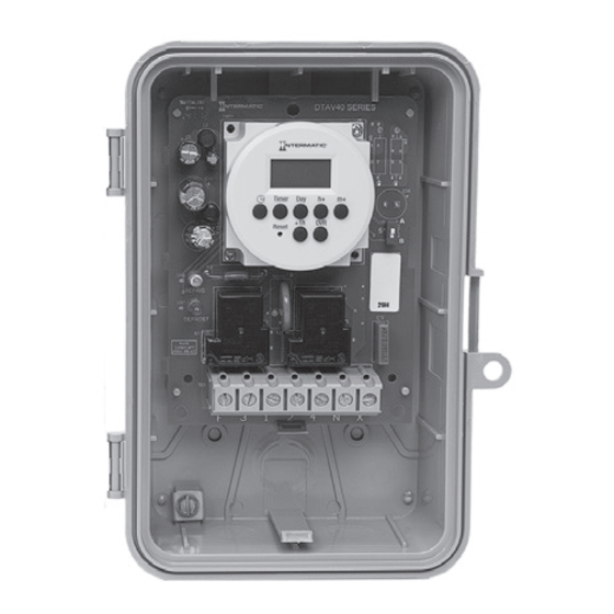
1. Open door and then remove interior protective cover by releasing
spring latch on bottom (Figure 1).
2. Apply corresponding Terminal Identification and Door labels-see
retrofit kit instructions.
3. Remove timer mechanism by releasing PCB Latch on bottom
(Figure 1).
4. Select knockouts to be used. Remove inner 1/2" knockout by
inserting a screwdriver in the slot and carefully punch knockout
loose. Remove slug. If 3/4" knockout is required, remove the outer
ring with pliers after removing the 1/2" knockout. Smooth edges
with knife if necessary, on plastic enclosure only.
5. Place enclosure in desired mounting location and mark the three
mounting holes (refer to Figure 2 for Type 3R below). Start by
installing top screw into mounting surface and hanging enclosure on
screw head through keyhole; then screw in remaining two screws
in bottom holes.
6. Grounding: Terminate all ground wires to ground lug on bottom of
enclosure.
7. Re-install timer in enclosure.
8. Replace interior protective cover.
Timer Mechanism
Interior
Protective
Cover
Spring Latch
PCB Latch
Type 3R Enclosure
Figure 1
6-1/8"
2-1/2"
Ground Lug
Type 3R Enclosure
Figure 2
Advertisement

Related Manuals for Intermatic DTAV40E2 Series


Summary of Contents for Intermatic DTAV40E2 Series
- Page 1 Bonding between conduit connections is not automatic and must be provided as part of the installation. (-15˚C to 40˚C) • When replacing a timer with a metal bracket, replace the bracket with a non-metallic bracket. (Intermatic Operating Humidity: 0 - 95% RH, Model DT-B is recommended).
- Page 4 SELECCIÓN DE MODO (INTERRUPTOR PLD S1): 5. Coloque la caja en la ubicación de montaje que desee y marque Primero determine qué modelo se está reemplazando (Intermatic o sus los tres orificios de montaje (consulte la Figura 2, para obtener competidores).
-
Page 7: Données Techniques
• Lors du remplacement d’une minuterie à support métallique, remplacer ce support par un support non DURABILITÉ ÉLECTRIQUE : métallique (de préférence par le modèle DT-B d’Intermatic). 50 000 actionnements à pleine charge • Pour les emplacements extérieurs, étanches à la pluie ou les emplacements mouillés, des entrées de conduit DIMENSIONS : qui sont conformes aux exigences de UL514B (norme pour les pièces de fixation pour conduit et boîtes de... -
Page 12: Limited Warranty
GARANTÍA LIMITADA Este servicio de garantía está disponible mediante (a) la devolución del producto al proveedor al que se le compró la unidad; o (b) el llenado de una reclamación de garantía en línea en www.intermatic.com. Esta garantía la otorga: Intermatic Incorporated, 1950 Innovation Way, Suite 300, Libertyville, IL 60048. Para obtener servicios de garantía, ingrese a: http://www.Intermatic.com o llame al 815-675-7000.
Need help?
Do you have a question about the DTAV40E2 Series and is the answer not in the manual?
Questions and answers