Intermatic EJ351, EJ353 - Programmable Wall Switch Security Timer Manual
- Installation and user instructions (2 pages) ,
- Owner's instruction manual (2 pages) ,
- Installation and user instructions (2 pages)
Advertisement
IMPORTANT NOTES
Your PROGRAMMABLE WALL SWITCH SECURITY Timer is designed to operate standard incandescent light bulbs or (thermally protected Class P ballast) fluorescent lighting ONLY. NOT FOR USE WITH COMPACT FLUORESCENT BULBS. It requires a minimum lamp load totalling 40 watts and can handle a maximum combination totalling 500 watts. It is NOT TO BE USED to operate MERCURY VAPOR LIGHTS, APPLIANCES, RADIOS, TVS, STEREOS, etc.
Separate dimmers and photoelectric switches cannot be used in combination with your timer. We recommend that your timer not be used with "PAR" or "R" type outdoor flood lamps or lamps larger than 150 watts, since currents generated during lamp burn-out could damage the timer. Your Timer generates radio energy and may in rare cases cause radio or television interference. Possible solutions include: readjusting the receiver's antenna, plugging the receiver into a different AC outlet or moving the receiver itself.
The EJ351C and EJ353C are intended for use in room temperature applications.
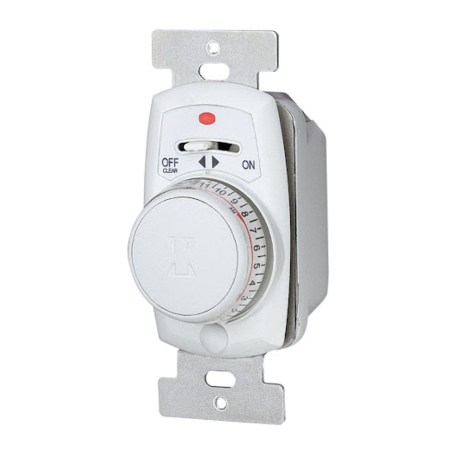
CONTROLS AND INDICATORS
MODEL EJ351 & EJ353

CONTROL LEVER. In OFF-CLEAR position all power is removed from timer and controlled light(s); this also clears the memory. In ON position, timer is in operation and is ready for programming.
PUSHBUTTON/TIME DIAL. Press once to turn lights on or off manually. Press twice quickly to switch from AUTOMATIC to MANUAL mode: press twice quickly again to switch back to AUTOMATIC mode. Rotate to set AUTOMATIC operation times or for review.
RED INDICATOR LIGHT. Indicates status of timer. When light is:
- FLASHING: Timer memory has been cleared and timer is ready to be programmed.
NOTE: Also PULSES momentarily when dial is rotated during RAPID PROGRAMMING or REVIEW. - OFF: Control lever is in OFF position or timer is in one of 3 modes: MANUALoperation; BEING PROGRAMMED, or in REVIEW.
- ON STEADY: Timer is programmed and in AUTOMATIC Mode.
AM or PM INDICATORS SHOWN ON THE DIAL, (shown in diffused area) are for reference during programming and review.
INSTALLATION
Your Timer replaces a standard toggle switch. It fits into a wall box easily and uses the same wires as the switch you took out. If you can install a wall switch, you can install the TImer. The only tools needed to install your timer are a flat blade screwdriver and a phillips head screwdriver. Carefully pull off the pushbutton time dial and remove the cover assembly from timer before proceeding with the installation.
- TURN POWER OFF to the wall switch by removing fuse or breaking the circuit.
- REMOVE SWITCHPLATE AND EXISTING SWITCH.
- MODEL EJ351 TIMER (See Fig. 2) Disconnect wires from old switch and connect them to the Timer. Use wire nuts provided. If old switch has ground wire (normally connected to green hex head screw) fasten it securely to metal box or to timer metal bracket.

Trim house bare wire to 7/16"; twist wire nut on both wires until it "locks" securely.- MODEL EJ353 (See FIg. 3) 3 way timer package contains the timer for either wall location and a short "jumper" wire for the other location. Identify and remove wire (usually black) attached to "common" terminal of old switch. This terminal normally has a different color screw or may be identified by markings on switch body. Connect to black lead of timer using wire nut. Remove the other two wires and connect one to the red and the other to the blue timer wire.

- MODEL EJ353 (See FIg. 3) 3 way timer package contains the timer for either wall location and a short "jumper" wire for the other location. Identify and remove wire (usually black) attached to "common" terminal of old switch. This terminal normally has a different color screw or may be identified by markings on switch body. Connect to black lead of timer using wire nut. Remove the other two wires and connect one to the red and the other to the blue timer wire.
- MOUNT TIMER into wall box, being careful not to cut wires on box edges, using flat head screws supplied.
- ALIGN WALL SWITCH PLATE with timer bracket by placing upper screw hole of plate over red indicator light.
- INSTALL CONTROL PANEL by inserting clear plastic lens in upper screw hole of plate. (Not applicable for decorator style switch plates). Install fillister dome head screw in bottom hole. Make sure the post next to the knob shaft is properly mated with the hole switch lever hole in the control panel. Tighten screw snug, but DO NOT OVER-TIGHTEN.
- INSTALL PUSHBUTTON TIME DIAL with flat side of control shaft aligned with flat in time dial and press ON. INSTALLATION IS COMPLETE FOR MODEL EJ351.
- Push plastic cover over bottom screw.
- INSTALL JUMPER WIRE at second 3 way location for MODEL EJ353 (See Figure 4 and 5).

NOTE: For new construction or to replace either a dimmer switch or a 3-way switch without screw terminals, a single pole switch can be used at the remote location.


NOTE: In a 3-way switch application, if the length of wire between two switches is over 30 feet, we recommend using timer model SS8.
BE CERTAIN POWER IS OFF.
Screw Terminal Switches: Remove plate and screws from second 3-way switch, pull switch from wall box. Identify "common" terminal and loosen screw just enough to install one end of the jumper under the screw head. Retighten screw. Loosen screw at either of the two other terminals and install other end of jumper wire. Retighten screw.
Reinstall switch and turn power back on. Turn timer on by moving control lever to on position. Try operating light using second (remote 3-way) switch. If the timer fails to work correctly, rewire the jumper to go from the "common" terminal to the other terminal. Reinstall switch and turn power back on. Both the remote switch and the timer should now be able to control the light. Snap small plastic cover over the bottom screw. Replace dimmer illuminated or back wire pressure terminal switches with a single pole non-dimmer switch. Identify the wire previously connected to the 3-way common; attach it together with one of the other wires, under either screw terminal of the new switch. Remaining wire should be attached under the other screw terminal. Turn power back on. Move control lever to ON (or BRIGHT). Operate remote 3-way switch, light should turn on and off from this switch. If not, TURN POWER OFF and move jumper wire and reconnect under the other terminal, together with the single wire already in place. Turn power back on and repeat test procedures.
PROGRAMMING YOUR ELECTRONIC IN-WALL TIMER
Programming can be accomplished in 2 ways
RAPID PROGRAMMING
Enables you to make desired time settings in just minutes. Achieved as follows:
- Move control lever to OFF-CLEAR for at least 5 seconds; red indicator light will go off, and all previous time settings will be cleared from memory. (If timer fails to set, leave in off position for 15 minutes.)
- Move lever to ON. RED INDICATOR will start FLASHING.
- Check a clock; then rotate time dial clockwise at least one click, stopping at the half hour nearest to present time. NOTE: When rotating time dial, do NOT accidentally PRESS at the same time. (While rotating dial, keep pressure, pulling out on the dial to avoid accidentally setting an incorrect time.)
- Press pushbutton once to enter present time. RED INDICATOR will go OFF, present time has now been recorded.
- Rotate time dial clockwise to desired ON time; RED light will PULSE momentarily with each click.
- Press pushbutton to enter ON time; controlled light(s) will turn on.
- Rotate dial to desired OFF time.
- Press pushbutton to enter OFF time; controlled light(s) will now be off.
- Repeat Steps 5-8 for each addition ON/OFF period.
- Continue to rotate time dial for at least 24 hours from the first ON time to complete this program, at which time the RED INDICATOR light will come ON and stay ON, indicating timer is in AUTOMATIC mode. NOTE: Dial does not rotate automatically after setting to indicate time of day.
24-HOUR SELF PROGRAMMING
Accomplished by use of the Timer as a standard light switch over a 24-hour period.
- Move control lever to OFF-CLEAR position for at least 5 seconds; RED INDICATOR light will go OFF, and previous time settings will be cleared from memory.
- Move lever to ON. RED INDICATOR light will start FLASHING.
- Turn light(s) on and off as you normally would during this 24 hour period. When you turn lights ON the first time, RED INDICATOR light will go OFF and remain OFF. However, if you should turn light(s) off in less than 30 minutes from the ON time, RED INDICATOR will resume FLASHING. Reason: Each on/off period must be at least 30 minutes.
At the end of the first 24 hour period, your Timer will be fully programmed, red indicator will stay ON and timer will automatically repeat the lighting pattern you entered during the 24 hours.
PROGRAM REVIEW enables you to determine the ON/OFF settings in your Timer memory. Proceed as follows:
- Timer must be in AUTOMATIC mode (RED INDICATOR light ON).
- Rotate time dial clockwise at least one click, stopping at nearest half hour to present time.
- Press pushbutton once to start review (RED INDICATOR will go OFF).
- Rotate time dial clock wise slowly observing time on dial when controlled light(s) go ON AND off (RED indicator will PULSE with each click).
- Press pushbutton once to end review (RED INDICATOR will go ON and stay ON. Timer is in AUTOMATIC mode.)
NOTE
Reviewing does not in any way altering the program. Once a program is stored it can be changed only by switching to OFF-CLEAR, which clears the entire memory.
TROUBLESHOOTING GUIDE
FOR TIMER WALL MODELS EJ351, EJ353
| SYMPTOM: | SOLUTION: |
|
|
|
|
|
|
|
|
|
|
| MODEL EJ353 ONLY: | |
|
|
SPECIAL NOTES
SWITCHING FROM AUTOMATIC TO MANUAL OPERATION MODE
If you wish to switch temporarily to MANUAL mode without disturbing the stored program, press the pushbutton quickly twice. The red indicator light will go off, you Timer is now in the MANUAL mode. Your controlled light(s) can be operated manually. To return to AUTOMATIC OPERATION mode, press the pushbutton quickly twice again; the red light will go on, indicating the timer is again in the AUTOMATIC mode.
YOUR Timer Is ALWAYS A LIGHT SWITCH
With the Timer in AUTOMATIC mode, you can use it as a conventional ON/OFF light switch just by pressing the pushbutton once each time you wish to turn the lights on or off. This overriding of the stored program will not disturb the next automatic operation; your light(s) still turn on or off at the next programmed setting.
BURNED-OUT BULBS
If a bulb controlled by your Timer should burn out, the red indicator light will go off, alerting you that you have a burned-out bulb, and that your timer will not operate automatically. To restore normal operations, move control lever to OFF-CLEAR position and replace light bulb. Now move lever back to ON position for EJ351 and EJ353 models, then re-program timer.
MODEL EJ353
This Timer may fail to operate if the remote switch is located 30 - wire feet or more from the timer.
Your New Electronic Timer can now be used to replace a Decorator (Rocker) style switch using any standard single or multi-gang switch plate.

Use with either toggle style or decorator style switch plate.
SPECIFICATIONS
- POWER SUPPLY REQUIREMENTS: Operates in series with 120 VAC, 60 Hz. incandescent lighting loads.
- LOAD CAPACITY, Incandescent or thermally protected (Class P) ballast Only: MODELS EJ351, EJ353 40-500 watts.
NOTE: Derate to 400 watts maximum when two or more Timers are installed in same wall box. For fluorescent control see caution note under IMPORTANT NOTES. - MINIMUM ON OR OFF PERIOD: 30 minutes.
- REPEAT CYCLE: 24 hours.
- DAILY OPERATIONS: Up to 48 (24 ON events and 24 OFF events).
- VARIABILITY: ON and OFF times automatically vary at least 7 minutes from the time programmed and at least 15 minutes from the previous day.
- POWER FAILURE MEMORY PROTECTION: In case of power failure, the Timers memory will be retained for a minimum of 15 minutes, depending upon conditions at time of power failure.

Documents / ResourcesDownload manual
Here you can download full pdf version of manual, it may contain additional safety instructions, warranty information, FCC rules, etc.
Download Intermatic EJ351, EJ353 - Programmable Wall Switch Security Timer Manual
Advertisement


Need help?
Do you have a question about the EJ351 and is the answer not in the manual?
Questions and answers