Table of Contents
Advertisement
Available languages
Available languages
Risk of Fire or Electric Shock
WARNING
•
Disconnect power at the circuit breaker(s) or disconnect switch(es) before installing or servicing.
•
More than one circuit breaker or disconnect switch may be required to de-energize the equipment before
servicing.
•
Installation and/or wiring must be in accordance with national and local electrical code requirements.
•
For 40 amp loads, use #8 AWG wire, rated 90° C min.
•
Bonding between conduit connections is not automatic and must be provided as part of the installation.
•
When replacing a timer with a metal bracket, replace the bracket with a non-metallic bracket. (Intermatic
Model DT-B is recommended).
•
For outdoor locations, raintight, or wet location, conduit hubs that comply with requirements of UL514B
(standard for fittings for conduit and outlet boxes) are to be used.
NOTICE
Risk of Damage to Timer
•
Rotate timer dial clockwise only.
•
Do not move the clock hands on the timer. Moving the clock hands can damage the timer.
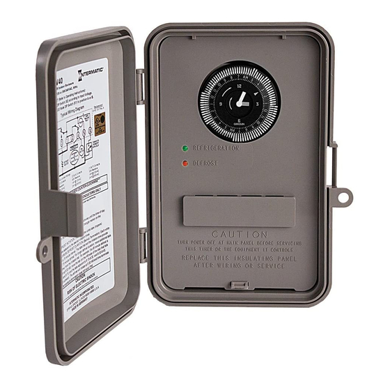
Mode Selection Switch (S1)
UL TYPE 3R ENCLOSURE
Set Mode Selection (See S1 DIP Switch, table and instructions below).
MODE SELECTION (S1 DIP SWITCH):
First determine what model is being replaced (Grasslin or Competitors).
The mode selector DIP switch (located at lower right side of the board)
determines the configuration of terminals 2 & 4. In position "A", the ter-
minals are normally closed, and will open during a defrost. In position "B",
terminals 2 & 4 are normally open, and will close during a defrost. Select
proper position from table below and wiring diagrams indicated.
To select mode simply slide the switch as follows:
Mode A - position switch up;
Mode B - position switch down;
Note: When Mode "B" is selected the
DTAV40 will operate as follows:
Refrigeration Mode - Red & Green LEDs
will turn OFF (1 & 3 and 2 & 4 break while
1 & F make)
Defrost Mode - RED & GREEN LEDs will turn
ON (1 & 3 and 2 & 4 make while 1 & F break)
Mode Selection
Paragon
Precision
TIME INITIATED, TIME TERMINATED
TIME INITIATED, REMOTE TEMPERATURE OR
PRESSURE TERMINATED
TIME INITIATED, PRESSURE TERMINATED
(Separate Pressure Switch Required (see instructions)
Grasslin
Cross Ref.
DTAV replaces over 40 models.
Installation &
Operating Instructions
DTAV40 Series
Time Initiated, Temperature, Pressure or
Time Terminated Auto-Voltage 40A Defrost Timers
(Saleable item DT-B)
SEE SEPARATE BRACKET
REPLACEMENT NOTICE
UL TYPE 1 ENCLOSURE
Wiring Diag.
INSTALLATION
1. Open door and then remove interior protective cover by releasing
spring latch on bottom (Figure 1). Cover flexes out easily on Type 1
metallic case (Figure 4).
2. Apply corresponding Terminal Identification and Door labels-see
retrofit kit instructions.
BRACKET MOUNT
3. Remove timer mechanism by releasing PCB Latch on bottom
(Figure 1). Timer Mechanism comes detached in TYPE-1 Metallic
Enclosure (Figure 4).
IN PACKAGE
4. Select knockouts to be used. Remove inner 1/2" knockout by
inserting a screwdriver in the slot and carefully punch knockout
loose. Remove slug. If 3/4" knockout is required, remove the outer
ring with pliers after removing the 1/2" knockout. Smooth edges
with knife if necessary, on plastic enclosure only.
5. Place enclosure in desired mounting location and mark the three
mounting holes (refer to Figure 2 for Type 3R and Figure 3 for
Type 1 below). Start by installing top screw into mounting surface
and hanging enclosure on screw head through keyhole; then screw
in remaining two screws in bottom holes.
6. Grounding: Terminate all ground wires to ground lug on bottom of
enclosure.
7. Re-install timer in enclosure.
8. Replace interior protective cover.
4-1/16"
SPECIFICATIONS:
Maximum Contact Switch Rating:
40A Resistive @ 120-240VAC
2HP @ 240VAC; 1HP @ 120VAC
WIRING CONNECTIONS:
Screw box lug terminals. Up to one #8AWG Wire
ENVIRONMENTAL RATINGS:
Operating Temperature Range: -40˚F to 104˚F
(-40˚C to 40˚C)
Operating Humidity: 0 - 95% RH,
non-condensing
ELECTRICAL LIFE:
50,000 Operations at Full Load
DIMENSIONS:
8.795" x 6.631" x 2.935" (H x W x D)
SHIPPING WEIGHT: 3 lbs.
AGENCY APPROVALS: UL LISTED
Timer Mechanism
Interior
Protective
Cover
Spring Latch
PCB Latch
Type 3R Enclosure
Figure 1
PCB Latch
7 ¾"
2-1/2"
5"
Type 1 Enclosure
Figure 3
6-1/8"
2-1/2"
Ground Lug
Type 3R Enclosure
Figure 2
TImer Mechanism
Interior
Type 1 Enclosure
Protective Cover
Figure 4
Advertisement
Table of Contents

Related Manuals for Intermatic DTAV40 Series


Summary of Contents for Intermatic DTAV40 Series
-
Page 1: Operating Instructions
Bonding between conduit connections is not automatic and must be provided as part of the installation. ENVIRONMENTAL RATINGS: • When replacing a timer with a metal bracket, replace the bracket with a non-metallic bracket. (Intermatic Operating Temperature Range: -40˚F to 104˚F Model DT-B is recommended). - Page 2 PROGRAMMING SYNCHRONOUS AND QUARTZ MODELS Follow the instructions in the sections below to program the DTAV40 TRIPPERS DTAV40 TROUBLESHOOTING GUIDE DTAV40 Timer. MODE M ODE Setting the Time of Day: In Refrigeration Mode Rotate the timer dial clockwise to align the triangle on the Arrow on timer points to current time.
- Page 3 DTAV40 - TYPICAL WIRING DIAGRAMS All switch positions are shown in refrigeration cycle operation, and change position upon initiation of a defrost. 8145 Replacement 8247 Replacement–Double Pole Switching 8041 Replacement Mode B with 8247 Terminal Block Label Applied Mode A - No Label Required Mode A with 8041 Terminal Block Label Applied CONTROL CONTROL...
-
Page 4: Especificaciones
• Cuando reemplace un temporizador que tenga un soporte de metal, reemplace el soporte por uno no metálico. (Se VIDA ELÉCTRICA: recomienda el modelo DT-B de Intermatic). 50.000 Operaciones a carga completa • Se deben usar ejes de conducto pluvífugos o para ubicaciones húmedas que cumplan los requisitos de la norma DIMENSIONES: UL514B (estándar para piezas para conductos y cajas de distribución) en ubicaciones al aire libre. - Page 5 PROGRAMACIÓN DE MODELOS SINCRÓNICOS Y DE CUARZO Siga las instrucciones descritas en las secciones que se presentan a GUÍA DE SOLUCIÓN DE DISPARADORES DEL DTAV40 continuación para programar el temporizador DTAV40. PROBLEMAS DEL DTAV40 MODO MODO Ajuste de la hora del día: En modo de refrigeración Gire el disco del temporizador en la dirección de las agujas del reloj El puntero en el temporizador apunta a la hora actual.
- Page 6 DTAV40 - DIAGRAMAS TÍPICOS DE CABLEADO Se muestran todas las posiciones de interruptores en la operación de ciclo de refrigeración y cambian su posición al momento de iniciar una descongelación. Reemplazo 8247, conmutación bipolar Reemplazo 8145 Reemplazo de 8141 Modo B con etiqueta aplicada del bloque de Modo A: No necesita etiqueta Modo A con etiqueta aplicada del bloque terminales 8247...
-
Page 7: Installation
Lors du remplacement d’une minuterie à support métallique, remplacer ce support par un support non DURABILITÉ ÉLECTRIQUE : métallique (de préférence par le modèle DT-B d’Intermatic). 50 000 actionnements à pleine charge Pour les emplacements extérieurs, étanches à la pluie ou les emplacements mouillés, des entrées de conduit •... - Page 8 PROGRAMMER LES MODÈLES SYNCHRONE ET QUARTZ GUIDE DE DÉPANNAGE DTAV40 Suivre les instructions dans les sections ci-dessous pour programmer la minuterie DTAV40. MODE Régler l’heure du jour : En mode Réfrigération Tourner le cadran de la minuterie dans le sens horaire pour aligner Flèche de minuterie pointée sur l’heure courante.
- Page 9 DTAV40 - SCHÉMAS DE CÂBLAGE TYPIQUES Tous les commutateurs sont représentés en position de réfrigération et changent de position lors du déclenchement d’un dégivrage. Remplacement de 8247 - Commutation bipolaire Remplacement de 8145 Remplacement de 8041 Mode B avec étiquette de bornier 8247 apposée Mode A - Aucune étiquette requise Mode A avec étiquette de bornier 8041 apposée ALIMENTATION...
- Page 10 DTAV40 Series FEATURES • DTAV40 replaces over 40 competitive models Time Initiated, Temperature, Pressure or Time • Auto-Voltage automatically adjusts for 120-240VAC Terminated Auto-Voltage 40 A Defrost Timers • Mounts in existing enclosures, no tools required • Box lug terminals •...
-
Page 11: Caractéristiques
Série DTAV40 CARACTÉRISTIQUES • La DTAV40 remplace plus de 40 modèles concurrents Minuterie de dégivrage 40 A à tension automatique, à déclenchement par horloge et • Réglage automatique de la tension de 120 à 240 V c.a. • Se monte sur les boîtiers existants sans outillage interruption par température, pression ou horloge •... - Page 12 LIMITED ONE-YEAR WARRANTY If within the warranty period specified, this product fails due to a defect in material or workmanship, Intermatic Incorporated will repair or replace it, at its sole option, free of charge. This warranty is extended to the original household purchaser only and is not transferable.
Need help?
Do you have a question about the DTAV40 Series and is the answer not in the manual?
Questions and answers