Intermatic EJ351 Owner's Instruction Manual
Intermatic ej351 timers: user guide
Hide thumbs
Also See for EJ351:
- User manual ,
- Installation and user instructions (2 pages) ,
- Installation and user instructions (2 pages)
Advertisement
158EJ11589
12/8/03
9:13 AM
Page 1
SWITCHING FROM AUTOMATIC TO MANUAL OPERATION MODE
If you wish to switch temporarily to MANUAL mode without disturbing the stored program,
press the pushbutton quickly twice. The red indicator light will go off, you Timer is now in the
MANUAL mode. Your controlled light(s) can be operated manually. To return to AUTOMATIC
OPERATION mode, press the pushbutton quickly twice again; the red light will go on, indicating the
timer is again in the AUTOMATIC mode.
YOUR Timer Is ALWAYS A LIGHT SWITCH
With the Timer in AUTOMATIC mode, you can use it as a conventional ON/OFF light switch just by
pressing the pushbutton once each time you wish to turn the lights on or off. This overriding of the
stored program will not disturb the next automatic operation; your light(s) still turn on or off at the next
programmed setting.
BURNED-OUT BULBS
If a bulb controlled by your Timer should burn out, the red indicator light will go off, alerting you that
you have a burned-out bulb, and that your timer will not operate automatically.
To restore normal operations, move control lever to OFF-CLEAR position and replace light bulb. Now
move lever back to ON position for EJ351 and EJ353 models, then re-program timer.
MODEL EJ353
This Timer may fail to operate if the remote switch is located 30 - wire feet or more from the timer.
Use with either toggle style or decorator style switch plate.
•
POWER SUPPLY REQUIREMENTS: Operates in series with 120 VAC, 60 Hz. incandescent
lighting loads.
•
LOAD CAPACITY, Incandescent or thermally protected (Class P) ballast Only: MODELS EJ351,
EJ353 40-500 watts.
NOTE: Derate to 400 watts maximum when two or more Timers are installed in same wall box. For
fluorescent control see caution note under IMPORTANT NOTES on page 1.
•
MINIMUM ON OR OFF PERIOD: 30 minutes.
•
REPEAT CYCLE: 24 hours.
•
DAILY OPERATIONS: Up to 48 (24 ON events and 24 OFF events).
•
VARIABILITY: ON and OFF times automatically vary at least 7 minutes from the time programmed
and at least 15 minutes from the previous day.
•
POWER FAILURE MEMORY PROTECTION: In case of power failure, the Timers memory will be
retained for a minimum of 15 minutes, depending upon conditions at time of power failure.
If within one (1) year from the date of purchase, this product fails due to a defect in material or workmanship,
Intermatic Incorporated will repair or replace it, at its sole option, free of charge. This warranty is extended to the
original household purchaser only and is not transferable. This warranty does not apply to: (a) damage to units
caused by accident, dropping or abuse in handling, acts of God or any negligent use; (b) units which have been
subject to unauthorized repair, opened, taken apart or otherwise modified; (c) units not used in accordance with
instructions; (d) damages exceeding the cost of the product ; (e) sealed lamps and/or lamp bulbs. LED's and
batteries; (f) the finish on any portion of the product, such as surface and/or weathering, as this is considered
normal wear and tear; (g) transit damage, initial installation costs, removal costs, or reinstallation costs.
INTERMATIC INCORPORATED WILL NOT BE LIABLE FOR INCIDENTAL OR CONSEQUENTIAL DAMAGES.
SOME STATES DO NOT ALLOW THE EXCLUSION OR LIMITATION OF INCIDENTAL OR CONSEQUENTIAL
DAMAGES, SO THE FOREGOING LIMITATION OR EXCLUSION MAY NOT APPLY TO YOU. THIS WARRANTY
IS IN LIEU OF ALL OTHER EXPRESS OR IMPLIED WARRANTIES. ALL IMPLIED WARRANTIES, INCLUDING
THE WARRANTY OF MERCHANTABILITY AND THE WARRANTY OF FITNESS FOR A PARTICULAR
PURPOSE, ARE HEREBY MODIFIED TO EXIST ONLY AS CONTAINED IN THIS LIMITED WARRANTY, AND
SHALL BE OF THE SAME DURATION AS THE WARRANTY PERIOD STATED ABOVE, SOME STATES DO NOT
ALLOW LIMITATIONS ON THE DURATION OF AN IMPLIED WARRANTY, SO THE ABOVE LIMITATION MAY
NOT APPLY TO YOU.
This warranty gives you specific legal rights and you may also have other rights which vary from state to state.
Warranty service is available by mailing postage prepaid to: Intermatic Incorporated/After Sales Service/7777 Winn
Rd., Spring Grove, IL 60081-9698/815-675-7000 http://www.intermatic.com Please be sure to wrap the product
securely to avoid shipping damage.
INTERMATIC INCORPORATED
SPRING GROVE, ILLINOIS 60081-9698
158EJ11589
SPECIAL NOTES
Your New Electronic Timer can now
be used to replace a Decorator
(Rocker) style switch using any
standard single or multi-gang switch
plate.
SPECIFICATIONS
WARRANTY
OWNERS INSTRUCTION MANUAL
This instruction sheet applies to the following PROGRAMMABLE WALL SWITCH SECURITY Timer
MODEL: EJ351 (Single Pole): For incandescent lights controlled from a single wall switch. For
fluorescent light control see IMPORTANT NOTES.
MODEL: EJ353 (Three-Way): Same as above for lights controlled from two locations.
Manufactured under one or more of the following patents: 4,274,045, 4,270,058, 4,344,000,
4,349,748, 4,360,739, 4,379,245, 4,439,688 and other patents pending.
IMPORTANT NOTES
Your PROGRAMMABLE WALL SWITCH SECURITY Timer is designed to operate standard
incandescent light bulbs or (thermally protected Class P ballast) fluorescent lighting ONLY.NOT FOR
USE WITH COMPACT FLUORESCENT BULBS. It requires a minimum lamp load totalling 40 watts
and can handle a maximum combination totalling 500 watts. It is NOT TO BE USED to operate
MERCURY VAPOR LIGHTS, APPLIANCES, RADIOS, TVS, STEREOS, etc.
Separate dimmers and photoelectric switches cannot be used in combination with your timer. We
recommend that your timer not be used with "PAR" or "R" type outdoor flood lamps or lamps larger
than 150 watts, since currents generated during lamp burn-out could damage the timer.
Your Timer generates radio energy and may in rare cases cause radio or television interference.
Possible solutions include: readjusting the receiver's antenna, plugging the receiver into a different
AC outlet or moving the receiver itself.
The EJ351C and EJ353C are intended for use in room temperature applications.
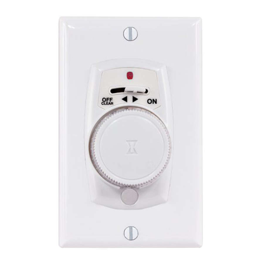
CONTROLS AND INDICATORS
MODEL EJ351 & EJ353 (See FIg.1)
CONTROL LEVER. In OFF-CLEAR position all power is removed from timer and controlled light(s);
this also clears the memory. In ON position, timer is in operation and is ready for programming.
PUSHBUTTON/TIME DIAL Press once to turn lights on or off manually. Press twice quickly to switch
from AUTOMATIC to MANUAL mode: press twice quickly again to switch back to AUTOMATIC
mode. Rotate to set AUTOMATIC operation times or for review.
RED INDICATOR LIGHT. Indicates status of timer. When light is,
1. FLASHING: Timer memory has been cleared and timer is ready to be programmed.
NOTE: Also PULSES momentarily when dial is rotated during RAPID PROGRAM-
MING or REVIEW.
2. OFF: Control lever is in OFF position or timer is in one of 3 modes: MANUAL
operation; BEING PROGRAMMED, or in REVIEW.
3. ON STEADY: Timer is programmed and in AUTOMATIC Mode.
AM or PM INDICATORS SHOWN ON THE DIAL, (shown in diffused area) are for reference during
programming and review.
Red Indicator
Light
Control Lever
Pushbutton Time Dial
(Does not Rotate
Automatically)
Solid State
Microprocessor
System
Control Panel
Plastic Screw Cover
INSTALLATION
Your Timer replaces a standard toggle switch. It fits into a wall box easily and uses the
same wires as the switch you took out. If you can install a wall switch, you can install the
TImer. The only tools needed to install your timer are a flat blade screwdriver and a
phillips head screwdriver. Carefully pull off the pushbutton time dial and remove the cover
assembly from timer before proceeding with the installation.
1. TURN POWER OFF to the wall switch by removing fuse or breaking the circuit.
2. REMOVE SWITCHPLATE AND EXISTING SWITCH.
3. MODEL EJ351 TIMER (See Fig. 2) Disconnect wires from old switch and connect them
to the Timer. Use wire nuts provided. If old switch has ground wire (normally
®
Advertisement

Related Manuals for Intermatic EJ351


Summary of Contents for Intermatic EJ351
-
Page 1: Installation
If within one (1) year from the date of purchase, this product fails due to a defect in material or workmanship, Intermatic Incorporated will repair or replace it, at its sole option, free of charge. This warranty is extended to the original household purchaser only and is not transferable. -
Page 2: Programming
Tighten screw snug, but DO NOT OVER-TIGHTEN. 7. INSTALL PUSHBUTTON TIME DIAL with flat side of control shaft aligned with flat in time dial and press ON. INSTALLATION IS COMPLETE FOR MODEL EJ351. 8. Push plastic cover over bottom screw.
Need help?
Do you have a question about the EJ351 and is the answer not in the manual?
Questions and answers