Advertisement
Quick Links
1
.
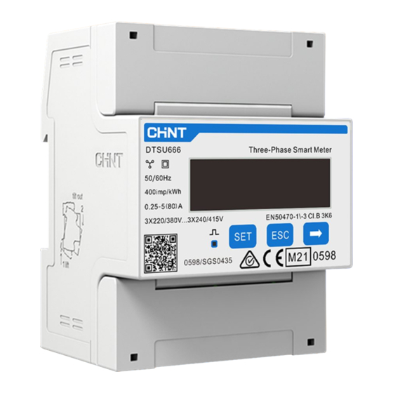
Overview
DTSU666 series three phase four wire electronic energy meter (din-rail) is designed based on power monitoring and energy metering
demands for electric power system, communication industry, construction industry, etc. as a new generation of intelligent instrument
combining measurement and communication function, mainly applied into the measurement and display for the electric parameters in the
electric circuit including three voltage, three current, active power, reactive power, frequency, positive&negative energy, four-quadrant
energy, etc. Adopting the standard DIN35mm din rail mounting and modular design, it is characterized with small volume, easy installation
and easy networking. It is compatible with Growatt Three-phase Storage/Hybrid Inverters.
2.
1.5(6)A
0.015A
0.5% of range maximum
3.
A
B
C
4.
TPM-CT-C-EU(DTSU666) Three-phase
TPM-CT-C-EU (DTSU666) Three-phase
Smart Meter Quick Guide
Smart Meter Quick Guide
Item
Number
Description
A
1
Three phase meter
B
1
User Manual
C
1
RS485 cable (standard length 15m)
D
D
3
Current Transformer
5.
Note:
1. The Growatt Storage Inverter and the Hybrid Inverter are hereinafter collectively referred to as "the Storage/Hybrid Inverter".
2. The grid is on the right side and the current flows from P1 to P2 (from the grid to the load).
PE
3
6
9
10
2 32 5 35 8 38 11 12
P2←P1
S2
L1
S2
Storage
S1
L2
/Hybrid
S2
S1
L3
Inverter
S1
N
RS485-B
RS485-A
13 14 16 17 19 21 24 25
1
4
7
10
A. Voltage sampling and power supply wiring
Wiring of the L1 voltage sampling line: corresponding to meter Pin 2;
Wiring of the L2 voltage sampling line: corresponding to meter Pin 5;
Wiring of the L3 voltage sampling line: corresponding to meter Pin 8;
Wiring of the N voltage sampling line: corresponding to meter Pin 10.
B. Current transformer wiring
Please refer to the diagram above. The grid is on the right and the
current flows from P1 to P2 (from the grid to the load).
Wiring of the L1 CT: S1 Line corresponding to meter Pin 1, S2 Line
corresponding to meter Pin 3;
Wiring of the L2 CT: S1 Line corresponding to meter Pin 4, S2 Line
corresponding to meter Pin 6;
Wiring of the L3 CT: S1 Line corresponding to meter Pin 7, S2 Line
corresponding to meter Pin 9.
C. RS485 cable wiring
Connect the RS485A to Pin 14 and RS485B to Pin 13 (The network
cables delivered with the inverter are labeled as 485-A and 485-B; if
you are using the cables purchased yourself, make sure to
differentiate between 485-A and 485-B.)
D. Connecting the meter to the Storage/Hybrid Inverter
COM1(6、7)
The system wiring diagram is shown as follows. In case that the meter is not
operating properly, you can refer to it to check the wiring. For the Growatt
Storage/Hybrid Inverter, please connect the meter to the COM1 port.
Grid-N
Grid-T
Primary load
Grid-S
Grid-R
S1
S2
Secondary load
S1
S2
P2:PCS
side
S1
AC
Breaker
P1:Grid
S2
side
Load
Breaker
Load-N
Load-T
Power cable
Load-S
Load-R
sample cable
EARTH
communication cable
Grid-PE
Load-PE
Main
LOAD
GRID
Breaker
7
COM1
6
Storage/Hybrid Inverter
E.
When connecting the smart meter to WIT, connect one end of
the cable to Terminal 13 (485B) and Terminal 14 (485A) of the
smart meter and the other end to Pin 6 (485A) and Pin 7 (485B) of
the COM1 port.
Note: In most cases, the red cable is used for 485A and the black
cable for 485B.
Grid
COM1
Red(484A)---COM1(6)
Black(484B)---COM1(7)
F. Dismantle the 16-pin connector delivered with WIT and set
aside the water-proof plug. Route the cables through each part
sequentially, then connect them to Pin 6 and Pin 7. Finally,
connect the connector to the COM1 port of the inverter.
G. The standard RS485 cable length is 15m. If a longer RS485
cable is required, please use an intact cable and make sure the
RS485 cable is less than 100m (the recommended length is less
than 25m).
Note:
1. Connect the L/N input and output cables correctly.
Please ensure that the input voltage and input current
are within the permissible range; otherwise the meter
will be damaged.
2. The input and output wires of the meter should be
correctly connected; otherwise, the meter will not be
able to operate properly.
Advertisement

Subscribe to Our Youtube Channel
Related Manuals for Growatt TPM-CT-C-EU


Summary of Contents for Growatt TPM-CT-C-EU
- Page 1 1. The Growatt Storage Inverter and the Hybrid Inverter are hereinafter collectively referred to as “the Storage/Hybrid Inverter”. combining measurement and communication function, mainly applied into the measurement and display for the electric parameters in the 2.
- Page 2 Service and contact Note: The communication address of the meter and the Growatt Three-phase Storage/Hybrid inverter is 04 by default, the baud rate is 9600. If the meter fails to communicate with the inverter, you can check the parameter settings by following the instructions: Shenzhen Growatt New Energy CO.,LTD...
Need help?
Do you have a question about the TPM-CT-C-EU and is the answer not in the manual?
Questions and answers