Table of Contents
Advertisement
Quick Links
INSTRUCTION MANUAL
DL200
DANGER
・ This instruction manual is for production engineers and maintenance
personnel in charge of operation of this product. When a beginner uses
this product, receive instructions from experienced personnel, the
distributor or our company.
・ Before installing, operating or maintaining this equipment, carefully
read this manual and the safety labels attached to the equipment.
Failure to follow these instructions and safety precautions could result
in serious injury, death, or property damage.
・ Store this manual near equipment for future reference.
・ If any questions related to safety arise about this manual, please
confirm them with the distributor or our company.
KITAGAWA IRON WORKS CO., LTD.
77-1 Motomachi, Fuchu, Hiroshima 726-8610 Japan
Dual Lock Chuck
TEL +81-(0)847-40-0526
FAX +81-(0)847-45-8911
Version 1.01 (2010.05.31)
Original instructions
type
Advertisement
Table of Contents

Related Manuals for Kitagawa DL200


Summary of Contents for Kitagawa DL200
- Page 1 ・ Store this manual near equipment for future reference. ・ If any questions related to safety arise about this manual, please confirm them with the distributor or our company. KITAGAWA IRON WORKS CO., LTD. 77-1 Motomachi, Fuchu, Hiroshima 726-8610 Japan TEL +81-(0)847-40-0526...
- Page 2 Preface This manual provides detailed information about how to safely and correctly use the power chuck (DL200 type) for a lathe. Before starting to use this power chuck, read this manual carefully and always follow the instructions and warnings in "Important Safety Precautions" and "Precautions for Use"...
- Page 3 The chuck and cylinder from Kitagawa Iron Works should be used together. If you must use a part not made by Kitagawa, check with us or our distributor to be sure it is safe to do so. We will not be responsible for injury, death, damage or loss caused by use of a chuck or cylinder made by another company unless this use has been approved by Kitagawa or its distributor.
-
Page 4: Table Of Contents
Table of Contents 1. Structural Drawing and Parts List -----------------------------------------------------------------------5 1-1. Type display 1-2. Structural drawing 1-3. Scope of product 1-4. Parts list ----------------------------------------------------------11 Important Safety Precautions 3. Specifications ----------------------------------------------------------------------------------------------19 3-1. Specifications 3-2. Relationship between gripping force and rotation speed 3-3. - Page 5 7. Malfunction and Countermeasures ------------------------------------------------------------------63 7-1. In the case of malfunction 7-2. Where to contact in the case of malfunction For Machine Tool Manufacturers (Chapter 8) 8. Attachment -------------------------------------------------------------------------------------------------65 8-1. Outline drawing of attachment 8-2. Manufacturing and attaching of draw bar 8-3.
-
Page 6: Structural Drawing And Parts List
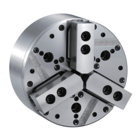
1. Structural Drawing and Parts List 1-1. Type display Type display as shown below Fig.1 1-2. Structural drawing Table 1 Type DL206 104.8 3-M10 22.5 M26×1.5 DL208 133.4 3-M12 37.5 M28×1.5 DL210 171.4 3-M16 38.5 24.5 39.5 M30×1.5 DL212 171.4 3-M16 33.5 19.5... - Page 7 Fig.2...
-
Page 8: Scope Of Product
1-3. Scope of product This instruction manual is for the chuck part. Fig.3 ・ To prevent the work from flying, safe design, maintenance and erroneous action prevention of the hydraulic system to maintain the gripping force of the chuck is extremely important. Thoroughly read the “Important Safety Precautions”... -
Page 10: Parts List
1-4. Parts list Fig.4... -
Page 12: Important Safety Precautions
Important Safety Precautions Important safety precautions are summarized below. Please read this section before first starting to use this product. Failure to follow the safety precautions below will result in DANGER ! serious injury or death. Turn off main power supply before attaching, inspecting or replacing chuck, and before adding oil. - Page 13 Important Safety Precautions Failure to follow the safety precautions below will result in DANGER ! serious injury or death. Do not allow the rotation speed of the chuck to exceed the maximum allowable speed limit. (Refer to pages 21-31) For All Users ・...
- Page 14 Important Safety Precautions Failure to follow the safety precautions below will result in DANGER ! serious injury or death. Keep the height of the jaw within the range specified in the gripping force limit table (Refer to pages 26-27). If you must use a jaw taller than a standard soft jaw, use less than the input (piston thrust force, draw bar drawing force) specified in the gripping force limit table.
- Page 15 Important Safety Precautions Failure to follow the safety precautions below will result in DANGER ! serious injury or death. Use of a chuck and cylinder that cannot be used together safely may cause the cylinder to break at high pressure resulting in the chuck and work flying out.
- Page 16 Important Safety Precautions Failure to follow the safety precautions below will result in DANGER ! serious injury or death. Always tighten the bolts at the specified torque. If the torque is insufficient or excessive, the bolt will break, which is dangerous as the chuck or work will fly out.
- Page 17 Important Safety Precautions Failure to follow the safety precautions below will result in DANGER ! serious injury or death. Provide sufficient strength for the draw bar (Refer to pages 67-68). Provide sufficient screw depth for the draw bar. Firmly tighten the draw bar. For Machine Tool Manufactures ・...
- Page 18 Important Safety Precautions Failure to follow the safety precautions below could result WARNING ! in serious injury or death. Do not modify the chuck in a way not permitted by the manufacturer. For All Users ・ It may not only break the chuck but the chuck and the work may fly out, which is dangerous.
- Page 19 Important Safety Precautions Failure to follow the safety precautions below could result WARNING ! in serious injury or death. If the T-nut is protruded from the master jaw, the T-nut and master jaw are damaged. Also, the jaw or work-piece will scatter, thus For All Users resulting in danger.
-
Page 20: Specifications
3. Specifications 3-1. Specifications Table 3 Outer gripping Type DL206 DL 208 DL 210 DL 212 Plunger stroke 11.5 11.5 Jaw stroke (in diameter) Allowable maximum input force (kgf) (1937) (3569) (5099) (5099) Maximum static gripping force (kgf) (5506) (8566) (11217) (11217) Minimum input force... - Page 21 Inner gripping Type DL206 DL 208 DL 210 DL 212 Allowable maximum 12.6 input force (kgf) (1285) (2379) (3365) (3365) 73.3 73.3 Maximum static gripping force (kgf) (3671) (5710) (7478) (7478) Maximum oil pressure (kgf/cm (17.3) (21.4) (23.5) (23.5) Reference: 1kN = 101.97kgf 1MPa = 10.197kgf/cm Type DL206...
-
Page 22: Relationship Between Gripping Force And Rotation Speed
・ The attaching bolts of the soft jaw are tightened at the specified torque. (Refer to page ・ The numerical values are obtained with the Kitagawa gripping force meter . The gripping position of the gripping force meter is at h ・... - Page 23 T-nut and the master jaw periphery are almost lined up. ・ The numerical values are obtained by the Kitagawa gripping force meter. The gripping position of the gripping force meter is at h To avoid serious accidents caused by the chuck or work flying out: ・...
- Page 24 Kitagawa gripping force meter is required. Fig.6 ・ In the case of processing a considerably unbalanced work, lower the rotation speed. The work will fly out and this is dangerous.
- Page 25 3-3. Relationship between gripping part center height, static griping force and input force / Relationship between top jaw mass moment and gripping force loss If the gripping part center height of the used top jaw (dimension H in Fig. 7) is higher than the gripping part center height of the standard soft jaw, a large load is applied to the master jaw, T nut, jaw attaching bolts, etc.
- Page 26 ・ Keep the height of the top jaw within the range of the gripping force limit table. (Refer to Fig.8-10) ・ If a top jaw is taller than the standard soft jaw, use it at the input force (piston thrust force, draw bar drawing force) specified in the gripping force limit table. If it is used without lowering the input, the chuck will break and this is dangerous as the chuck and work will fly out.
- Page 27 3. Determination of static gripping force Fg Determine the static gripping force F by considering the required conditions such as the distortion of the workpiece and strength of the jaw. However, the gripping force F should be F or less. g2(max) 4.
- Page 28 Fig.9 Fig.10...
- Page 29 5. Calculation of set hydraulic pressure Q × P= P - loss) loss Q cyl(max) Pmax Qcyl(max) loss P :Cyl. Set hydraulic pressure (MPa) Type (MPa) (kN) (MPa) P :Max. permissible hydraulic pressure of Y1020R 0.25 Y1225R 0.25 cyl. (MPa) Y1530R 0.25 Q...
- Page 30 6. Calculation of increment Δ(m × r) of jaw mass moment The increment Δ(m × r) of mass moment for the used jaw against the standard soft jaw is calculated. (Fig.11) It can also be found even if the mass moment m ×...
- Page 31 7. Calculation of centrifugal force F N F max max × ⎛ ⎞ Type N π -1 × × × × ⎜ ⎟ (kN) ΔF=Δ m (min ) ⎝ ⎠ 1000 DL206 6000 DL208 5000 N × × F=F +ΔF μ...
- Page 32 ・ If the chuck is used at a gripping force exceeding the maximum permissible gripping force, the chuck will be damaged and the workpiece will scatter. ・ When it is difficult to calculate the dynamic gripping force, rotate the chuck at as low a rotating speed as possible.
-
Page 33: Forming Soft Jaw
4. Forming Soft Jaw 4-1. Attachment of soft jaw The attaching position of the soft jaw can be adjusted by loosening the socket head cap screw, attaching the soft jaw and by changing each serration engagement position. Use the most appropriate soft jaw considering the shape, dimension, material, and surface roughness of the work and the cutting conditions, etc. - Page 34 Table 4 Bolt size Tightening torque N・m N・m N・m N・m N・m N・m N・m N・m...
- Page 35 Fig.14...
- Page 36 Fig.15...
- Page 37 ・ Use the T nut and the attaching bolts attached to the chuck and do not use bolts other than these. If commercially available bolts are used for an unavoidable reason, use bolts at the strength classification 12.9 (strength classification 10.9 for M22 or more) or more, and pay sufficient attention to the length.
- Page 38 ・ Check that the reference mark on the side of the No. 1 master jaw is within the range of the entire stroke as shown in Fig. 17. Full stroke the jaw at least once a day to check it before work or when supplying grease, etc. If it goes out of the range of appropriate stroke due to loosening of the draw screw, etc., the work may not be gripped, and this is dangerous as the work will fly out.
-
Page 39: Forming Jaw
・ When the gripping center height becomes as low as possible, the gripping force, retract motion and accuracy are stable and this will result in stable production. ・ The high jaw and wide jaw increase mass. A jaw where the mass is large increases the gripping force loss because of centrifugal force by chuck rotation, and cutting conditions become disadvantageous. -
Page 40: Forming Soft Jaw With Outside Diameter Gripping
4-3. Forming soft jaw with outside diameter gripping 1. Preparation of the plug for forming Prepare the plug for forming. The surface roughness of the plug ・ outside diameter is to be approximately 25s, and make a shape with sufficient thickness which does not distort. It is convenient to prepare various outside diameter dimensions ・... -
Page 41: Forming Soft Jaw With Inside Diameter Gripping
6. Trial cutting Remove the plug for forming and grip the work to check the jaw ・ stroke. Implement trial cutting to check the process precision and that ・ there is no slip, etc. ・ Contacting on the gripping surface is to be 2 points contact of the side A and the side B when gripping. - Page 42 5. Forming ・ Process the gripping part (dimension φD’) of the work in the state that the ring is kept gripped. The φD’ part is to be approximately the same diameter (H7) as the diameter of the gripping part of the work, and process to be surface roughness at 6s or less.
-
Page 43: Jaw With Grooves / Jaw With Grip Piece
As a result, it becomes large and a great load will be applied to the jaws, T-nut and mounting bolts. If there is no choice but to use the jaw with grooves or grip pieces, contact Kitagawa. Fig.18 Fig.19 ・... -
Page 44: Usage
5. Usage This product is a device to fix a work-piece when it is processed by the lathe machine or the rotary table. The rotary cylinder closes the jaw and fixes a work-piece so that it does not move during processing. -
Page 45: Precautions During Gripping Work In Irregular Shape
5-3. Precautions related to usage of jaw ・ If a soft jaw other than one made by Kitagawa Iron Works is used, the engagement will be inferior, and the master jaw will be deformed, the gripping precision will worsen, and the work will fly out due to gripping failure, which is dangerous. -
Page 46: Precautions Related To Processing
5-4. Precautions related to processing <1> Unbalance ・ In the case of processing largely unbalanced work, lower the rotation speed. The work will fly out and this is dangerous. ・ Vibrations are generated if there is unbalance owing to the work or the jig, etc. Vibration not only will impart a negative influence on the process precision but also the endurance of the chuck being remarkably shortened, and the chuck may break. -
Page 47: Attachment Of Locator And Jig
5-5. Attachment of locator and jig The locator is required for the DL chuck. The DL chuck grips the workpiece in the chuck radial direction and simultaneously, presses the workpiece to the locator. Prepare a locator that has the shape, dimensions, accuracy, material and quenching suitable for production of the workpiece. In the case of attaching the locator and the jig on the chuck body surface, tap or drill a hole in the additional process range specified in Fig.21. - Page 48 Fig.20-2 2. Seating spec. locator and air feed tube Fig. 20-3 shows an example of a locator in the seating spec. The air feed tube is mounted to the spindle back to supply air or coolant for seating to the locator. Fig.20-3...
- Page 49 3.Additional machining for cover ・ When the rotary direction of the locator is positioned by boring pin holes additionally on the chuck surface, the cover can be additionally machined. The cover used is made of refining material (HS30 - 35). Pay attention to tools and cutting conditions in the case of additional machining.
-
Page 50: Change Of Inner/Outer Diameter Gripping
・ Pay attention so that a drill tip does not penetrate the cover. ・ Additional machining is to be pin holes. Never cut the cover remarkably. ・ Take care so that the cover is not deformed by additional machining. 5-6. Change of inner/outer diameter gripping 1. - Page 51 Fig,22 ・ When the workpiece is gripped with the input force to the plunger set to the push side, there is a danger because the inside of the chuck is damaged, the gripping force is low and the workpiece will scatter. ・...
- Page 52 2. Change steps of inner/outer diameter gripping 1. Unclamp the jaws (Plunger: advanced) and turn off the main power of the machine before starting work. 2. Remove the jaws and locator. 3. Clean the chuck surface and periphery so that chips or coolant will not enter into the inside of the chuck.
- Page 53 Fig.23 Fig.24...
-
Page 54: Dust-Proof Measures
5-7. Dust-proof measures Although the DL chuck has a dust-proof function, neither a cutting chip nor coolant can be shut out 100%. When the chuck is used where significant chips or coolant exists, or where it is hard to discharge the chips at the vertical lathe or stationery cylinder, take measures for forming the locator that mounts the scraper or consider a chip discharge. -
Page 55: Adjustment Of Retracting Amount
・ In the standard shipping state, flat spring of 1 is inserted with a long seat faced to the spindle side. When KITAGAWA manufactures and ships the jaws or locators for a specific workpiece production, various types such as the direction being opposite to 1, or 2 or 3 type is included are provided for optimal setting. - Page 56 ・ Take care so that the rear body is not damaged. ・ When excessively retracted or a problem is not solved even if it is adjusted, contact KITAGAWA.
-
Page 57: Maintenance And Inspection
3. Grease to use ・ Use the designated grease specified in Table 6. If grease other than the designated grease is used, sufficient effect may not be obtained. Table 6 Genuine Kitagawa genuine product CHUCK GREASE PRO product (Kitagawa distributor of each country) - Page 58 4. Frequency of lubrication ・ Add grease once every two months. ・ In the case of high rotation or in the case of using a large amount of water soluble coolant, increase the frequency of lubrication according to the usage conditions. ・...
-
Page 59: Disassembling
6-3. Disassembling Disassembling procedures Read the following disassembling procedures with reference to pages 9-10. 1. Turn off the main power of the machine before starting work. 2. Loosen the jaw attaching bolt [21] and remove the soft jaw [12] and the T nut [11]. 3. - Page 60 ・ Use an eyebolt or a hanging belt when attaching and detaching the chuck to and from the machine, as there is a danger of injury or damage if the chuck drops. Chuck size Eyebolt (inch) 6 , 8 , 10 ・...
- Page 61 ・ Remove the eyebolt or the belt without fail after using. If the chuck is rotated with the eyebolt, etc., attached, they may fly out and this is dangerous. ・ Disassemble and clean the chuck at least once every 6 months or every 100,000 strokes (once every 2 months or more for cutting cast metal).
- Page 62 2. Replacement of O-ring ・ If the DL chuck is used, the O-ring is worn. Moreover, if chips are caught in the slide way, the O-ring may be damaged. An O-ring like this must be replaced. ・ In particular, the O-ring [33] of the socket part located on the upper surface of the seal [13] is worn intensely because it is exposed to the harsh environment of chips and coolant.
- Page 63 Fig.28 Table 6 φB φC Type (mm) (mm) (mm) (mm) (mm) DL206 DL208 DL210 DL212 Fig.29...
-
Page 64: Malfunction And Countermeasures
7. Malfunction and Countermeasures 7-1. In the case of malfunction Check the points specified in the table below and take the appropriate countermeasure. Table 7 Defective Cause Countermeasure The chuck inside will break. Disassemble and replace the broken part. The chuck The sliding surface is seized. -
Page 65: Where To Contact In The Case Of Malfunction
Defective Cause Countermeasure Workpiece deformed excessive Reduce gripping force in a range where processing is possible. gripping force. Because gripping center height is too high, Precision jaw is deformed or mounting bolt is Lower the jaw height. extended. failure. Jaws and locator formed by chuck except for Form the jaws and locator using the chuck being used. -
Page 66: Attachment
For Machine Tool Manufactures Following pages are described for machine tool manufacturers (personnel who attach a chuck to a machine). Please read following instruction carefully when you attach or detach a chuck to machine, and please sufficiently understand and follow the instructions for safe operation. - Page 67 ・ Attach the manual switching valve at a position where it is easy to operate for the attaching equipment. ・ Install the hydraulic unit at a position where the drain hose is not kinked and the needle of the pressure gauge is easily read. ・...
- Page 68 8-2. Manufacturing and mounting of draw bar 1. Production of draw bar Determine the length of the draw bar as shown below. Fig.31 Fig.32 Table 8 Type Cylinder A B C D E F G L DL206 Y1020R M26×1.5 M-72.5 DL208 Y1225R M28×1.5...
- Page 69 both ends and the inner periphery do not swing or become unbalanced. ・ Provide sufficient strength for the Draw bar. If the Draw bar is broken due to insufficiency of the strength, the gripping force will be lost instantly, which is dangerous as the work will fly out.
- Page 70 ・ Use the bolts attached to the chuck, and do not use other bolts. However, if you must use other bolts not provided by Kitagawa, use bolts that have at least a strength classification of 12.9 (10.9 for M22 or more) and be sure they...
-
Page 71: Attachment Of Chuck
Table 9 Bolt size Tightening torque N・m N・m N・m N・m N・m N・m N・m N・m 8-3. Attachment of chuck 1. Attaching the draw bar to the cylinder ・ Apply adhesive onto the screw part of the draw bar, and screw it into the piston rod of cylinder. - Page 72 ・ Use an eyebolt or a hanging belt when attaching and detaching the chuck to and from the machine, as there is a danger of injury or damage if the chuck drops. Chuck size Eyebolt (inch) 6 , 8 , 10 ・...
- Page 73 ・ Use the bolts attached to the chuck, and do not use other bolts. However, if you must use other bolts not provided by Kitagawa, use bolts that have at least a strength classification of 12.9 (10.9 for M22 or more) and be sure they are long enough.
- Page 74 5. Adjust the position of the wedge plunger ・ Full stroke the jaw and check that the reference mark of the master jaw is completely within the entire stroke area (Refer to Fig.35). ・ To prevent the plunger from contact with the body with the jaw opened, rotate the joint handle counterclockwise.
-
Page 75: Other Information
9. Other information 9-1. About standards and orders This product is based on the following standards or orders. ・ Machinery directive:2006/42/EC Annex I ・ EN ISO 12100-1:2003+A1:2009 ・ EN ISO12100-2+A1:2009 ・ EN ISO14121-1:2007 ・ EN1550:1997+A1:2008 9-2. Information about markings of product Fig.36 9-3.About disposal Ultimate disposal of this product should be handled according to all national laws and... - Page 76 The products herein are controlled under Japanese Foreign Exchange and Foreign Trade Control Act. In the event of importing and/or exporting the products, you are obliged to consult KITAGAWA as well as your government for the related regulation prior to any transaction.
Need help?
Do you have a question about the DL200 and is the answer not in the manual?
Questions and answers