Table of Contents
Advertisement
INSTRUCTION MANUAL
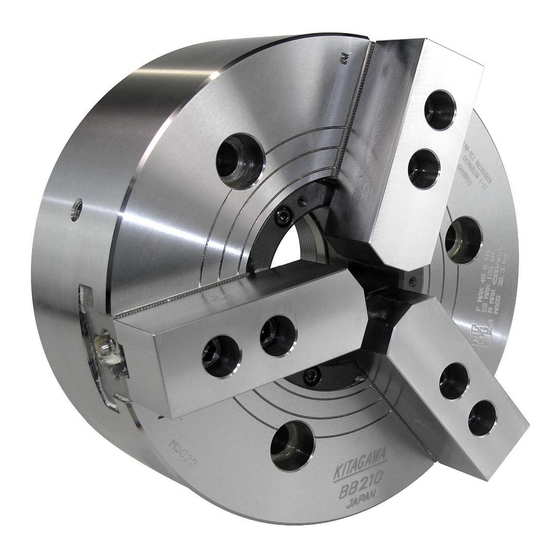
BB200
Large Thru-Hole Power Chuck
・This instruction manual is for production engineers and
maintenance personnel in charge of operation of this product.
When a beginner uses this product, receive instructions from
experienced personnel, the distributor or our company.
・Before installing, operating or maintaining this equipment,
carefully read this manual and the safety labels attached to
the equipment. Failure to follow these instructions and safety
precautions could result in serious injury, death, or property
damage.
・Store this manual near equipment for future reference.
・If any questions related to safety arise about this manual,
please confirm them with the distributor or our company.
Kitagawa Corporation
77-1,Motomachi,Fuchu-shi,Hiroshima,726-8610,Japan
Te l . +81-847-40-0561
Fax. +81-847-45-8911
Version 1.11 (2019.09.03)
Original instructions
type
Advertisement
Table of Contents

Related Manuals for Kitagawa BB200 Series


Summary of Contents for Kitagawa BB200 Series
- Page 1 ・Before installing, operating or maintaining this equipment, carefully read this manual and the safety labels attached to the equipment. Failure to follow these instructions and safety precautions could result in serious injury, death, or property damage. ・Store this manual near equipment for future reference. ・If any questions related to safety arise about this manual, please confirm them with the distributor or our company. Kitagawa Corporation 77-1,Motomachi,Fuchu-shi,Hiroshima,726-8610,Japan Te l . +81-847-40-0561 Fax. +81-847-45-8911...
- Page 2 The chuck and cylinder from Kitagawa Corporation should be used together. If you must use a part not made by Kitagawa, check with us or our distributor to be sure it is safe to do so. We will not be responsible for injury, death, ...
-
Page 3: Table Of Contents
Table of Contents 1. Structural Drawing and Parts List ……………………………………………………………… 3 1-1. Type display 1-2. Structural drawing 1-3. Scope of product 1-4. Parts list Important Safety Precautions ………………………………………………………… 6 3. Specifications …………………………………………………………………………………… 12 3-1. Specifications 3-2. Relationship between gripping force and rotation speed 3-3. Relationship between gripping part center height, static griping force and input force / Relationship between top jaw mass moment and gripping force loss 4. Forming Soft Jaw ……………………………………………………………………………… 17 4-1. Attachment of soft jaw 4-2. Forming soft jaw with outside diameter gripping 4-3. Forming soft jaw with inside diameter gripping 4-4. Forming method when you use forming jig 5. Usage …………………………………………………………………………………………… 21 5-1. Precautions during gripping work with chuck 5-2. Precautions during gripping work in irregular shape 5-3. Precautions related to usage of jaw 5-4. Precautions related to processing 5-5. Attachment of locator and jig 6. Maintenance and Inspection ………………………………………………………………… 23 6-1. Periodic Inspection 6-2. Grease lubrication 6-3. Disassembling 7. Malfunction and Countermeasures …………………………………………………………… 25 7-1. In the case of malfunction 7-2. Where to contact in the case of malfunction For Machine Tool Manufacturers (Chapter 8) 8. Attachment ……………………………………………………………………………………… 26 8-1. Outline drawing of attachment 8-2. In the case that the back plate must be manufactured (BB200 series) 8-3. In the case of with back plate (BB200A series) -
Page 4: Structural Drawing And Parts List
1 . Structural Drawing and Parts List 1−1 Type display Type display as shown below B B 2 0 6 A 5 9 9 9 BB200 series Chuck nominal diameter (inch) Attachment shape Straight spigot joint:− −5 :A5 −6 :A6 −8 :A8 −11 :A1 −15(Former JIS) : C5 −15(New JIS):K5 Design No. Fig.1 1−2 Structural drawing Body Master jaw Top jaw (Soft jaw. hard jaw. special jaw included) Back plate Plunger nut Cover T nut Attaching bolt Draw nut... -
Page 5: Scope Of Product
1−3 Scope of product This instruction manual is for the chuck part. Cylinder Chuck Drain hose Flexible hose Pressure adjusting Hydraulic Pressure Manual screw pump gauge switching valve SOL. Line Filter Solenoid valve Tank Fig.3 WARNING ・ To prevent the work from flying, safe design, maintenance and erroneous action prevention of the hydraulic system to maintain the gripping force of the chuck is extremely important. Thoroughly read the Important Safety Precautions on and after page 6 in this manual. -
Page 6: Parts List
1−4 Parts list 20 13 19 12 18 11 21 14 Fig.4 Table 1 Part name Quantity Part name Quantity Body Jaw attaching bolt Wedge plunger Chuck attaching bolt Master jaw Set screw Soft jaw Steel ball T nut Grease nipple Plunger nut Hex key Draw nut Hex key Cover Hex key Hex key Coil spring Handle Socket head button screw Back plate Socket head cap screw 6 or 9 Socket head cap screw 22, 23 are only supplied if there is a back plate. -
Page 7: Important Safety Precautions
2 . Important Safety Precautions Important safety precautions are summarized below. Please read this section before first starting to use this product. DANGER Failure to follow the safety precautions below will result in serious injury or death. Turn off main power supply before attaching, inspecting or replacing chuck, and before adding oil. For All Users ・The chuck may start rotation suddenly, and a part of the body or clothing may be Main power supply caught. Lathe Close door before rotating spindle. For All Users ・If the door is not closed, you may touch the rotating chuck or the work may fly out, ... - Page 8 DANGER Failure to follow the safety precautions below will result in serious injury or death. Do not allow the rotation speed of the chuck to exceed the maximum allowable speed limit. (Refer to pages 12-16) For All Users ・If the rotation speed of the chuck exceeds the rotation speed limit, this is very dangerous as the chuck and work will fly Fly out out. Work The input force of the chuck (piston thrust, pulling force of the draw pipe) must not exceed the allowable maximum input force. For All Users (Refer to pages 12-16) ・Input must match the specification of Cylinder the chuck. Draw pipe ・Adjust the hydraulic pressure to the cylinder so that the input force, which ...
- Page 9 Important Safety Precautions DANGER Failure to follow the safety precautions below will result in serious injury or death. Keep the height of the jaw within the range specified in the gripping force limit table (Refer to page 15). If you must use a jaw taller than a standard soft jaw, use less than the input (piston For All Users thrust force, draw pipe drawing force) specified in the gripping force limit table. ・Do not use a jaw of a height out of Standard soft Special top jaw height jaw height the range of the gripping force limit table or a jaw with mass moment out Lower the hydraulic of the range of the gripping force pressure when using limit table. The chuck will break and a tall jaw the chuck and work will break and fly ...
- Page 10 DANGER Failure to follow the safety precautions below will result in serious injury or death. Use of a chuck and cylinder that cannot be used together safely may cause the cylinder to break at high pressure resulting in the chuck For All Users and work flying out. ・Check that the chuck and the cylinder are in the safe combination when using at high pressure with our company or the distributor. Especially when the cylinder of our company and a high pressure chuck of other company are combined, confirmation is necessary. Cylinder Chuck ・If one of the abnormal events shown below occurs during operation, ...
- Page 11 Important Safety Precautions DANGER Failure to follow the safety precautions below will result in serious injury or death. Provide sufficient strength for the draw pipe (Refer to pages 27-28). Provide sufficient screw depth for the draw pipe. For Machine Tool Manufactures Firmly tighten the draw pipe. ・If the draw pipe break, the gripping force is instantly lost and this is dangerous as work will Cylinder adapter Draw pipe fly out. Cylinder Chuck ・If the screw depth of the draw pipe is insufficient, the screw will break and the gripping force will be lost instantly, and this is dangerous as work will fly out.
- Page 12 Important Safety Precautions WARNING Failure to follow the safety precautions below could result in serious injury or death. Do not modify the chuck in a way not permitted by the manufacturer. For All Users ・It may not only break the chuck but the chuck and the work may fly out, which is dangerous. ・If you attach a locator or jig on the chuck body surface, only process work in an acceptable range (Refer to page 22). Periodically supply adequate grease (Refer to page 23). Turn off power before adding grease. For All Users ・Insufficient grease supply lowers the gripping force, causes operation failure due ...
-
Page 13: Specifications
The power chuck has a mechanism to convert input force (piston thrust force, draw pipe drawing force) from the cylinder to gripping force. Therefore, the gripping force when the allowable maximum input force becomes the maximum static gripping force. However, the gripping force is different depending on the state of grease lubrication, grease in use, height of the jaw, etc. The maximum static gripping force specified in the specification is the value under the following conditions: standard soft jaw ・The Kitagawa standard soft jaw is used as the jaw. ・The attaching bolts of the soft jaw are tightened at the specified torque. (Refer to page 9) ・The numerical values are obtained with the Kitagawa gripping force meter . The gripping position of the Allowable maximum gripping force meter is at a position 1/2 of the height of input force the soft jaw top surface (height from the chuck surface to the top surface of the jaw). -
Page 14: Relationship Between Gripping Force And Rotation Speed
Fig. 6 shows relationships between the rotation speed and the centrifugal force when using the standard soft jaw. The centrifugal force differs significantly depending on the size and shape of the top jaw and the attaching position, therefore, when the rotation speed is high, actual measurement using a Kitagawa gripping force meter is required. -
Page 15: Relationship Between Gripping Part Center Height, Static Griping Force And Input Force / Relationship Between Top Jaw Mass Moment And Gripping Force Loss
BB210 limit limit 4500 3500 2000 4000 2000 4000 Rotation Speed:min - Rotation Speed:min - (r.p.m) (r.p.m) Fig.6 DANGER ・In the case of processing a considerably unbalanced work, lower the rotation speed. The work will fly out and this is dangerous. ・Vibration is generated if there is unbalance due to the work and the jig, etc. Vibration decreases process precision and shortens the working life of the chuck, even possibly breaking it. Correct the unbalance by using a balance weight, etc., or lower the rotation speed for use. ・In the case of heavy cutting at high rotation speed, vibration is easily generated in the same manner as the unbalance of the chuck, therefore, set the cutting conditions appropriate for the dynamic gripping force and machine rigidity. 3-3 Relationship between gripping part center height, static griping force and input force / Relationship between top jaw mass moment and gripping force loss If the gripping part center height of the used top jaw (dimension H in Fig. 7) is higher than the gripping part center height of the standard soft jaw, a large load is applied to the master jaw, T nut, jaw attaching bolts, etc. To prevent these parts from being broken, it is necessary to use the machine by using a lower input force than the allowable maximum input force. Additionally, if the top jaw is larger and heavier, the centrifugal force generated at the top jaw will increase. It is necessary to examine the dynamic gripping force considering the centrifugal force and to use the machine at a rotation speed that can withstand the cutting force. - Page 16 BB206 Input force Limit 17.2 0 Standard soft top jaw Standard soft top jaw Gripping part center height H (㎜) Mass moment of top jaw m×r×3 ( ㎏ ・㎜) Input force BB208 Limit 0 Standard soft top jaw Standard soft top jaw Mass moment of top jaw Gripping part center height H (㎜) m×r×3 ( ㎏ ・㎜) Input force BB210 Limit 12kN 22.2 0 Standard soft top jaw Standard soft top jaw Gripping part center height H (㎜) Mass moment of top jaw m×r×3 ( ㎏ ・㎜) BB212 Input force Limit...
- Page 17 NOTICE Analysis of the gripping force, input force and rotation speed using Fig. 8 is carried out as shown below. ・For example, in the case of BB206 standard soft jaw (mass moment 59.1kg・mm), it cannot exceed 6000min (rpm), and the gripping force loss due to the centrifugal force at this rotation speed is 39kN (approx. 3977kgf). The required static gripping force for the dynamic gripping force (gripping force loss by static gripping force - centrifugal force) to become 1/3 of the static gripping force is 58.5kN, and the required input to obtain this gripping force is 20kN. However, it is necessary to use at the gripping part center height H=17.2 mm or less.
-
Page 18: Forming Soft Jaw
4 . Forming Soft Jaw 4−1 Attachment of soft jaw The attaching position of the soft jaw can be adjusted by loosening the socket head cap screw, attaching the soft jaw and by changing each serration engagement position. Use the most appropriate soft jaw considering the shape, dimension, material, and surface roughness of the work and the cutting conditions, etc. DANGER ・Use the T nut so that it does not come out from the master jaw. (Refer to Fig.9) ・It if the T nut comes out from the master jaw, the master jaw and T nut will break causing the work to fly out and a possible precision failure. Hard jaw T nut Body Body Body (Correct) Fig.9 ・Always tighten the bolts at the specified torque. If the torque is insufficient or excessive, the bolt will break, which is dangerous as the chuck or work will fly out. Table 3 Bolt size Tightening torque Bolt size Tightening torque Bolt size Tightening torque M 5 7.5 N ・ m 107 N ・ m 539 N ・ m M 6 13 N ・ m 171 N ・... -
Page 19: Forming Soft Jaw With Outside Diameter Gripping
4−2 . Forming soft jaw with outside diameter gripping 1.Preparation of the plug for forming ・Prepare the plug for forming. The surface roughness of the plug outside diameter is to be approximately 25s, and make a shape with sufficient thickness which does not distort. ・It is convenient to prepare various outside diameter dimensions for dimensions of forming parts. ・It is convenient to process tapping in the center part of the plug and to guide with a bolt, etc. -
Page 20: Forming Soft Jaw With Inside Diameter Gripping
4−3 Forming soft jaw with inside diameter gripping 1.Preparation of the ring for forming ・Prepare the ring for forming. The surface roughness of the ring inside diameter is to be approximately 25s, and make a shape with a sufficient thickness which does not distort. ・It is convenient to prepare various inside diameter dimensions for dimensions of forming parts. 2.Process of the ring gripping part for forming ・Operate the switch valve and minimize the jaw to close. ・Then, process the φD part (part to grip the ring for forming). Set the dimension φD so that gripping near the center of the jaw maximum stroke (diameter) is possible. -
Page 21: Forming Method When You Use Forming Jig
4−4 Forming method when you use forming jig 1.Preparation of the jig for forming Ex.1 Ex.2 Plate ・Prepare the jig for forming. (There is a commercially available product.) ・Attach the pin (Example 1) or the bolt and nut (Example 2) by dividing equally into 3 portions onto the ring shape plate. Make the Protrusion ring into a shape with sufficient thickness which does not distort. Bolt and nut 2.Gripping of the jig for forming ・Operate the switch valve and maximize the opening of the jaw. Then, operate the switch valve to insert the jig for forming into the ... -
Page 22: Usage
・If the protrusion of the work is long, support it with a center or the steady rest. If the protrusion is long the tip of the work turns, and this is dangerous as the work will fly out. 5−3 Precautions related to usage of jaw DANGER ・If a soft jaw other than one made by Kitagawa Corporation is used, the engagement will be inferior, and the master jaw will be deformed, the gripping precision will worsen, and the work will fly out due to gripping failure, which is dangerous. ・Do not use a top jaw with a different serration pitch from the master jaw. The engagement of the crests of the serration will become insufficient, therefore, the serration crests will break when gripping the work, and this is ... - Page 23 5−4 Precautions related to processing DANGER <1> Unbalance ・In the case of processing largely unbalanced work, lower the rotation speed. The work will fly out and this is dangerous. ・Vibrations are generated if there is unbalance owing to the work or the jig, etc. Vibration not only will impart a negative ...
-
Page 24: Maintenance And Inspection
6−2 Grease lubrication 1.Position to lubricate ・Lubricate using a grease gun from the grease nipple on the body periphery part or each master jaw periphery part. Supply grease when the jaw is open. After lubrication, repeat opening and closing the jaw several times without gripping work. 2.Grease to use ・Use the designated grease specified in Table 6. If grease other than the designated grease is used, sufficient effect may not be obtained. Table 6 Genuine Kitagawa genuine product CHUCK GREASE PRO product (Kitagawa distributor of each country) Kitagawa chuck grease Conventional product Molykote EP Grease TORAY Dow Corning (only inside Japan) Conventional Chuck EEZ grease Kitagawa-Northtech Inc. (North American region) product MOLYKOTE TP-42... -
Page 25: Disassembling
6−3 Disassembling Disassembling procedures Read the following disassembling procedures with reference to page 5. 1. Turn off the main power of the machine before starting work. 2. Loosen the jaw attaching bolt [13] and remove the soft jaw [4] and the T nut [5]. 3. Remove the cover [8]. 4. Turn the draw nut [7] with the handle [10] while loosening the chuck attaching bolt [14], and remove the chuck from the spindle. 5. Remove the wedge plunger [2] to the chuck rear side. 6. Remove the master jaw [3] to the inner periphery side of the chuck. 7. Assemble again while sufficiently coating the recommended grease in the reverse procedures of disassembling. At this time, pay sufficient attention so as not to make a mistake in the numbers of the body [1], master jaw [3], and the wedge plunger [2]. 8. Refer to page 30 about the installation procedure. (8-4. Attachment of chuck). CAUTION ・Use an eyebolt or a hanging belt when attaching and detaching the chuck to and from the machine, as there is a danger of injury or damage if the chuck drops. Chuck size(inch) Eyebolt 6,8,10 WARNING ・Remove the eyebolt or the belt without fail after using. If the chuck is rotated with the eyebolt, etc., attached, they may fly out and this is dangerous. ・Disassemble and clean the chuck at least once every 6 months or every 100,000 strokes (once every 2 months or more for cutting cast metal). If cutting powder or other substances stagnate inside the chuck, it will lead to insufficient stroke and a drop in the gripping force, and this is dangerous as the work will fly out. Check each part ... -
Page 26: Malfunction And Countermeasures
7 . Malfunction and Countermeasures 7−1 In the case of malfunction Check the points specified in the table below and take the appropriate countermeasure. Table 7 Defective Cause Countermeasure The chuck inside will break. Disassemble and replace the broken part. Disassemble, correct the seized part with oilstone, etc., or replace The chuck The sliding surface is seized. the part. does not Check the piping and the electric system, and if there is no operate. The cylinder is not operating. abnormality, disassemble and clean the cylinder. A large amount of cutting powder is inside. Disassemble and clean. Insufficient The draw pipe loosened. Remove the draw pipe and retighten it again. stroke of the jaw. Adjust so that the jaw is near the center of the stroke when The stroke of the jaw is insufficient. gripping the work. The gripping force is insufficient. Check that the correct hydraulic pressure is obtained. The forming diameter of the top jaw is not Form again based on the correct forming method. consistent with the work diameter. Calculate the cutting force and check that it is suitable for the The Work The cutting force is too large. specification of the chuck. slips. Supply grease from the grease nipple, and open and close the jaw Insufficient grease lubrication several times without gripping a work. The rotation speed is too high. Swinging occurs ... -
Page 27: Attachment
For Machine Tool Manufactures Following pages are described for machine tool manufacturers (personnel who attach a chuck to a machine). Please read following instruction carefully when you attach or detach a chuck to machine, and please sufficiently understand and follow the instructions for safe operation. 8 . Attachment 8−1 Outline drawing of attachment Cylinder adaptor Lathe rear cover Cylinder Top jaw Draw pipe Sleeve body NC lathe Chuck Support Back plate Flexible hose Drain hose Use one with large inside diameter as possible Pressure Hydraulic pump Manual Pressure gauge switching valve ajusting screw SOL. Line filter Solenoid valve Tank Return onto the oil surface Fig.13 ・Attach the manual switching valve at a position where it is easy to operate for the attaching equipment. ・Install the hydraulic unit at a position where the drain hose is not kinked and the needle of the pressure gauge is easily read. - Page 28 DANGER ・When other actuators are operated by the same hydraulic pressure source as the cylinder for chuck, be sure that a pressure drop of the cylinder does not occur during use. A hydraulic pressure drop leads to a drop in the gripping force which could allow the work to fly out. ・As to the drain hose ・Use one with inside diameter φ32. ・Use a transparent vinyl hose for visualization. ・Provide a stream slope, without air pocket. This will ensure no back pressure. ・The end of the hose is physically above the oil level. (Refer to Fig.13) ・If the hydraulic oil stagnates inside the cylinder, oil leakage occurs, which may cause a fire. WARNING ・Install after removing the dust inside the pipe completely. ・Add a filter to the pressure supply line. If foreign matters gets inside the cylinder, this is dangerous since the rotation valve of the cylinder will seize, the hose will tear off, and the cylinder will rotate. This is also dangerous ...
- Page 29 The dimension L in Fig.14 is determined from the distance A between the cylinder adapter and the back plate. (Example) In the combination of BB206, SS1543K, and when A=800mm, the draw pipe length L is to be L = A + 36 = 800 + 36 = 836mm. At the time of the screw process of the dimension a, the precision is to be JIS 6H and 6h, 6g matching the screw of the piston of the cylinder. Pay attention so that the thread parts on both ends and the inner periphery do not swing or become unbalanced. DANGER ・Provide sufficient strength for the draw pipe. If the draw pipe is broken due to insufficiency of the strength, the gripping force will be lost instantly, which is dangerous as the work will fly out. ・Keep the dimension e and the dimension f in Fig. 14 for the draw pipe and a material with the tensile strength 380MPa (38kgf/mm ) or more must be used. ・The personnel who designed draw pipe must judge whether the strength of the draw pipe is sufficient for the usage conditions. ・The dimensions and materials specified in this manual do not guarantee that the draw pipe will not break under every usage condition. ・If the screw-in depth of the draw pipe to the draw nut is insufficient, the screw will break and the gripping force will be lost instantly, which is dangerous as the work will fly out. ・If the engagement of the screw of the draw pipe is loose, vibration may occur resulting in breakage of the screw. If the screw breaks, the gripping force will be lost instantly, which is dangerous as the work will fly out.
- Page 30 DANGER ・Always tighten the bolts at the specified torque. If the torque is insufficient or excessive, the bolt will break, which is dangerous as the chuck or work will fly out. ・Use the bolts attached to the chuck, and do not use other bolts. However, if you must use other bolts not provided by Kitagawa, use bolts that have at least a strength classification of 12.9 (10.9 for M22 or more) and be sure they are long enough. Table 9 Bolt size Tightening torque Bolt size Tightening torque M 5 7.5 N ・ m 171 N ・ m M 6 ...
- Page 31 DANGER ・Always tighten the bolts at the specified torque. If the torque is insufficient or excessive, the bolt will break, which is dangerous as the chuck or work will fly out. ・Use the bolts attached to the chuck, and do not use other bolts. However, if you must use other bolts not provided by Kitagawa, use bolts that have at least a strength classification of 12.9 (10.9 for M22 or more) and be sure they are long enough. Table 11 Bolt size Tightening torque Bolt size Tightening torque M 5 7.5 N ・ m 171 N ・ m M 6 ...
-
Page 32: Attachment Of Chuck
8−4 Attachment of chuck 1.Attaching the draw pipe to the cylinder ・Apply adhesive onto the screw part of the draw pipe, and screw it into the piston rod of cylinder. At this time, refer to the instruction manual for the cylinder for tightening torque. NOTICE ・When attaching the draw pipe to the cylinder, the stopper pin of the piston may break if tightened at the stroke middle position of the piston. In the case of a SS type cylinder and SR type cylinder, screw it in so that the piston rod is fully out. Follow the explanation of the instruction manual for the cylinder for other items about the cylinder. 2.Attach the cylinder to the spindle (or the cylinder adapter) ・Check the run-out of the cylinder, and if it is normal, attach the hydraulic pipe. ・Move 2 to 3 times at low pressure (0.4 MPa-0.5 MPa, 4 - 5 kgf/cm ) and set the piston at the forward end and turn off the power supply. CAUTION Chuck size(inch) Eyebolt 6,8,10 ・Use an eyebolt or a hanging belt when attaching and detaching the chuck to and from the machine, as there is a danger of injury or damage if the chuck drops. WARNING ・Remove the eyebolt or the belt without fail after using. If the chuck is rotated with the eyebolt, etc., attached, they may fly out and this is dangerous. 3.Connect the chuck to the draw pipe ・Remove the soft jaw and the cover of the chuck, and insert the handle to the chuck center hole, to connect to the draw pipe while turning the draw nut. ・When connecting the draw nut and the draw pipe, do not forcibly screw them in if they cannot be screwed smoothly, ... - Page 33 DANGER ・ Always tighten the bolts at the specified torque. If the torque is insufficient or excessive, the bolt will break, which is dangerous as the chuck or work will fly out. ・Use the bolts attached to the chuck, and do not use other bolts. However, if you must use other bolts not provided by Kitagawa, use bolts that have at least a strength classification of 12.9 (10.9 for M22 or more) and be sure they are long enough. Table 13 Bolt size Tightening torque Bolt size Tightening torque M 5 7.5 N ・ m 171 N ・ m M 6 ...
-
Page 34: Other Information
9 . Other information 9−1 About standards and orders This product is based on the following standards or orders. ・ Machinery directive : 2006/42/EC Annex I ・ EN ISO 12100 : 2010 ・ EN1550 : 1997+A1 : 2008 9−2 Information about markings of product F MAX:MAX PERMISSIBLE INPUT FORCE ΣS MAX:MAX SIATIC GRIPPONG FORCE N MAX:MAX PERMISSIBLE SPEED MASS:MASS Manufacturer's logo Type of Jaw No. top jaw Manufacturer's Specifications address Type MFG No. Jaw No. Stroke mark Fig.21 9−3 About disposal Ultimate disposal of this product should be handled according to all national laws and regulations. - Page 36 Kitagawa Corporation Kitagawa Global hand Company 77-1,Motomachi,Fuchu-shi,Hiroshima,726-8610,Japan Tel.+81-847-40-0561 Fax.+81-847-45-8911 ■ JAPAN DOMESTIC 1-405-1,Kita-ku,Yosino-cho,Saitama-shi,Saitama,331-9634,Japan Tokyo office Tel.+81-48-667-3469 Fax.+81-48-663-4678 4-15-13,Yamatomachi,Wakabayashi-ku,Sendai-shi,Miyagi,984-0042,Japan Sendai office Tel.+81-22-232-6732 Fax.+81-22-232-6739 2-62,Kamitakabata,Nakagawa-ku,Nagoya-shi,Aichi,454-0873,Japan Nagoya office Tel.+81-52-363-0371 Fax.+81-52-362-0690 3-2-9,Kitakagaya,Suminoe-ku,Osaka-shi,Osaka,559-0011,Japan Osaka office Tel.+81-6-6685-9065 Fax.+81-6-6684-2025 77-1,Motomachi,Fuchu-shi,Hiroshima,726-8610,Japan Hiroshima office Tel.+81-847-40-0541 Fax.+81-847-46-1721 7-6-39,Itazuke,Hakata-ku,Fukuoka-shi,Fukuoka,812-0888,Japan Kyushu office Tel.+81-92-501-2102 Fax.+81-92-501-2103 77-1,Motomachi,Fuchu-shi,Hiroshima,726-8610,Japan Overseas office Tel.+81-847-40-0526 Fax.+81-847-45-8911 ■ OVERSEAS KITAGAWA-NORTHTECH INC.
Need help?
Do you have a question about the BB200 Series and is the answer not in the manual?
Questions and answers