Table of Contents
Advertisement
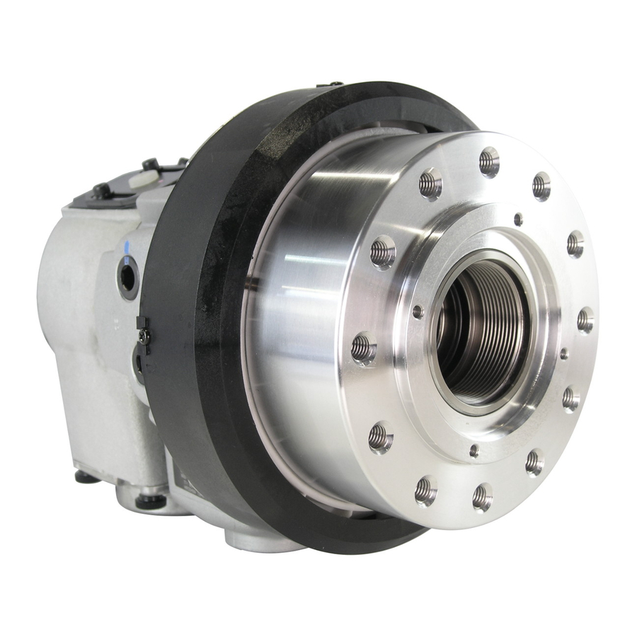
INSTRUCTION MANUAL
HIGH SPEED ROTARY HYDRAULIC
CYLINDER OPEN CENTER
・This instruction manual is for production engineers and
maintenance personnel in charge of operation of this product.
When a beginner uses this product, receive instructions from
experienced personnel, the distributor or our company.
・Before installing, operating or maintaining this equipment,
carefully read this manual and the safety labels attached to
the equipment. Failure to follow these instructions and safety
precautions could result in serious injury, death, or property
damage.
・Store this manual near equipment for future reference.
・If any questions related to safety arise about this manual,
please confirm them with the distributor or our company.
Kitagawa Corporation
77-1,Motomachi,Fuchu-shi,Hiroshima,726-8610,Japan
S
type
Te l . +81-847-40-0561
Fax. +81-847-45-8911
Version 1.10 (2019.09.03)
Original instructions
Advertisement
Table of Contents


Need help?
Do you have a question about the S1036 and is the answer not in the manual?
Questions and answers