Table of Contents
Advertisement
Quick Links
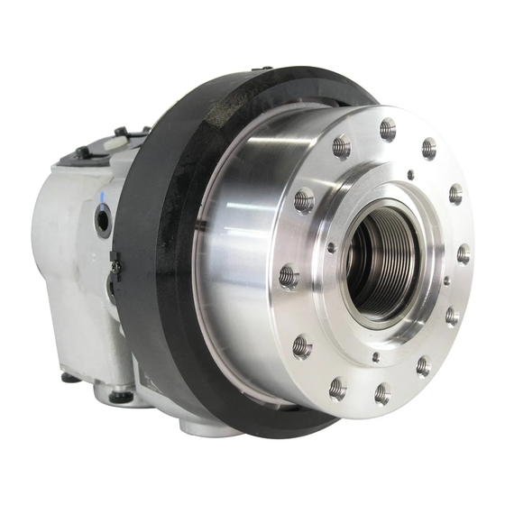
INSTRUCTION MANUAL
YW
ROTARY HYDRAULIC CYLINDER
・This instruction manual is for production engineers and
maintenance personnel in charge of operation of this product.
When a beginner uses this product, receive instructions from
experienced personnel, the distributor or our company.
・Before installing, operating or maintaining this equipment,
carefully read this manual and the safety labels attached to
the equipment. Failure to follow these instructions and safety
precautions could result in serious injury, death, or property
damage.
・Store this manual near equipment for future reference.
・If any questions related to safety arise about this manual,
please confirm them with the distributor or our company.
Kitagawa Corporation
77-1,Motomachi,Fuchu-shi,Hiroshima,726-8610,Japan
type
CLOSED CENTER
Te l . +81-847-40-0561
Fax. +81-847-45-8911
Version 1.09 (2019.09.03)
Original instructions
Advertisement
Table of Contents

Related Manuals for Kitagawa YW Series


Summary of Contents for Kitagawa YW Series
- Page 1 ・Before installing, operating or maintaining this equipment, carefully read this manual and the safety labels attached to the equipment. Failure to follow these instructions and safety precautions could result in serious injury, death, or property damage. ・Store this manual near equipment for future reference. ・If any questions related to safety arise about this manual, please confirm them with the distributor or our company. Kitagawa Corporation 77-1,Motomachi,Fuchu-shi,Hiroshima,726-8610,Japan Te l . +81-847-40-0561 Fax. +81-847-45-8911...
- Page 2 The chuck and cylinder from Kitagawa Iron Works should be used together. If you must use a part not made by Kitagawa, check with us or our distributor to be sure it is safe to do so. We will not be responsible for injury, death, ...
-
Page 3: Table Of Contents
Table of Contents 1.Structural Drawing and Parts List …………………………………………………………… 3 1-1. Type display 1-2. Structural drawing 1-3. Scope of product 1-4. Parts list . Important Safety Precautions 2 ……………………………………………………… 7 3.Specifications ………………………………………………………………………………… 14 3-1. Specification table 4.Hydraulic Oil …………………………………………………………………………………… 15 5.Trial Operation ……………………………………………………………………………… 15 6.Proximity switch ……………………………………………………………………………… 16 6-1. Specifications 6-2. Adjusting the position of a proximity switch 7.Maintenance and Inspection ……………………………………………………………… 17 7-1. Maintenance and inspection of cylinder 7-2. Maintenance and inspection of hydraulic unit 7-3. List of seals to use 8.Malfunction and Countermeasures ………………………………………………………… 18 8-1. In the case of malfunction 8-2. Where to contact in the case of malfunction For Machine Tool Manufacturers (Chapter 9) 9.Attachment …………………………………………………………………………………… 19 9-1. Outline drawing of attachment 9-2. Production and attachment of cylinder adapter 9-3. Production and attachment of draw bar and draw pipe 9-4. Attachment of cylinder 9-5. Tightening torque of cylinder attaching bolt 10.About Hydraulic Circuit Design …………………………………………………………… 24 11.Other Information ... -
Page 4: Type Display
1 . Structural Drawing and Parts List 1-1. Type display Type display as shown below Example 5th digit and after that are not displayed for the standard cylinders. 1. YW Abbreviated name of YW cylinders 2. 12 Nominal inside diameter of the cylinder 3. 25 Nominal piston stroke 4. R Cylinder with lock valve, relief valve RE Cylinder with lock valve, relief valve and proximity switch 5〜7 Columns for special specification for each destination of delivery Remarks 1) What is a lock valve ? This is a valve which has a function to retain the hydraulic pressure inside a cylinder temporarily when the pump pressure suddenly lowers as a result of blackout, malfunction of the hydraulic pump, etc. Remarks 2) What is a relief valve ? This is a valve which has a function to stop damage when the hydraulic oil filled inside the cylinder has increased its pressure due to the volume change. Cylinder adapter Sleeve Cylinder 1-2. Structural drawing Lathe YW-R type Support Detector Sleeve Cylinder Cylinder adapter YW-RE type Lathe Support Fig.1... -
Page 5: Scope Of Product
1-3. Scope of product This instruction manual is for the cylinder part. Chuck Cylinder NC lathe Drain hose Flexible hose Pressure Pressure gauge Hydraulic pump adjusting screw Manual switching SOL. valve Line filter Solenoid valve Tank Fig.2 WARNING ・To prevent the work from flying, safe design, maintenance and erroneous action prevention of the hydraulic system to maintain the gripping force of the chuck is extremely important. Thoroughly read the Important ... -
Page 6: Parts List
1-4. Parts list YW-R type 9 7 2 8 1 6 4 5 Fig.3 Table 1 Part name Quantity Part name Quantity Lock valve Relief valve O-ring Cylinder Piston A O-ring Piston B O-ring Rotary valve O-ring O-ring Sleeve Sleeve cover O-ring Cover O-ring Name plate O-ring Plug B Oil seal Nylon cap Guide pin Nylon cap Guide pin Plug Retaining ring Bearing... - Page 7 YW-RE type 3 33 38 17 36 40 22 14 2 24 15 9 8 18 34 39 1 20 7 4 6 26 5 10 27 Fig.4 Table 2 Part name Quantity Part name Quantity Lock valve Socket head button screw Relief valve O-ring Detector PAD O-ring Cylinder O-ring Piston A O-ring Piston B...
-
Page 8: Important Safety Precautions
2 . Important Safety Precautions Important safety precautions are summarized below. Please read this section before first starting to use this product. DANGER Failure to follow the safety precautions below will result in serious injury or death. Turn off main power supply before attaching, inspecting or replacing cylinder, and before adding oil. For All Users ・The cylinder may start rotation suddenly, and a part of the body Main power supply or clothing may be caught. OFF Lathe Close door before rotating spindle. For All Users ・If the door is not closed, you may touch the rotating chuck or the work may fly out, which is very dangerous. (In general, the safety interlock function which allows rota- Close tion ... - Page 9 DANGER Failure to follow the safety precautions below will result in serious injury or death. Do not allow the rotation speed of the chuck to exceed the maximum allowable speed limit. For All Users ・If the rotation speed of the chuck exceeds Fly out the rotation speed limit, this is very dan- gerous as the chuck and work will fly out. Work The input force of the chuck (piston thrust, pulling force of the draw pipe) must not exceed the allowable maximum input force. For All Users ・Input must match the specification of Cylinder the chuck. Draw pipe ・Adjust the hydraulic pressure to the Fly out cylinder so that the input, which deter- mines the gripping force of the chuck, does not exceed. ・Excessive ...
- Page 10 DANGER Failure to follow the safety precautions below will result in serious injury or death. Always tighten the bolts at the specified torque. (Refer to page 23) For All Users ・If the torque is insufficient or ex- cessive, the bolt will break, which Back plate is dangerous as the cylinder or work will fly out. ・Fix the lathe spindle or the cylin- der when you tighten bolts. Your hand could slip and get injury when ...
- Page 11 Important Safety Precautions DANGER Failure to follow the safety precautions below will result in serious injury or death. Use of a chuck and cylinder that cannot be used together safely may cause the cylinder to break at high pressure resulting in the For All Users chuck and work flying out. ・Check that the chuck and the cylinder are in the safe combination when using at high pressure with our company or the distributor. Especially when the cylinder of our company and a high pressure chuck of other company are combined, confirmation is necessary. ・If one of the abnormal events shown below occurs during operation, immediately stop the machine and consult with our company or the distributor. Cylinder Draw pipe ・The work slips. ・Loss of accuracy. Fly out ・The work begins to chatter. ・The machine's vibration significantly increases. ・The gripping force does not rise even if hydraulic pressure is raised. Work Chuck Use a cylinder with a lock valve (safety valve, check valve) incorporated in case of...
- Page 12 DANGER Failure to follow the safety precautions below will result in serious injury or death. The draw-bar and draw-pipe must have enough strength. (Refer to pages 21-22) The draw-bar and draw-pipe must have enough screw-in depth. The draw-bar and draw-pipe must be tightened surely. Apply adhesive to the thread part of the draw bar and For Machine Tool Manufactures screw it in at the specified torque. ・ If the draw-bar or draw-pipe is broken, a gripping force is lost instantaneously, causing the workpiece to fly out. ・ If the draw-bar or draw-pipe is screwed in inadequately, the screw is broken and a gripping force is lost instantaneously, causing the workpiece to fly out. ・ If the draw-bar or draw-pipe is unbalanced, the vibration occurs and the screw is broken, and then a gripping force is lost instantaneously, causing the workpiece to fly out. ・ When screwing the draw bar or draw pipe, piston to the end of the pull side stroke. ・ If the draw-bar or draw-pipe screw is meshed loosely, the vibration occurs or the screw is broken. If the screw is broken, a gripping force is lost instantaneously, causing the workpiece to fly out. ・ When the screw is loosened, the jaw stroke of the chuck becomes shorter and this is very dangerous as the work will fly out. Cylinder adapter Chuck Draw pipe Cylinder Draw bar Back plate Piston Thread size Tightening torque 100 N ・ m M42×1.5 130 N ・ m...
- Page 13 Important Safety Precautions WARNING Failure to follow the safety precautions below could result in serious injury or death. Do not modify the cylinder. For All Users ・Doing so may damage the cylinder and cause oil leakage which could result in a fire. And if the hydraulic oil leaks, the gripping force of the chuck will lower and the work may fly out, which is dangerous. ・Do not attach additional machining such as screws. ・Do not detach parts of the cylinder from the cylinder. Do not rotate the cylinder without hydraulic pressure. For All Users ・Doing so could cause seizing inside the cylinder, leading to a drop in the gripping force of the chuck. This is dangerous as work will fly out. Periodically add hydraulic oil. Turn off power and use designated hydraulic oil. (Refer to page 15) For All Users ・If supplying of the hydraulic oil is insufficient, the operation speed may lower and the thrust force will become insufficient resulting in a drop in the gripping force of the chuck, which is dangerous as the work may fly out.
- Page 14 Medication Alcohol Do not attach the other than parts manufactured by Kitagawa Iron Works to the cylinder. (Refer to pages 5-6, Fig.3-4) For Machine Tool Manufactures ・Doing so may damage the cylinder and cause oil leakage which could result in a fire. And if the hydraulic oil leaks, the gripping force of the chuck will lower and the work may fly out, which is ...
-
Page 15: Specifications
3 . Specifications 3-1. Specifications table Table 3 YW-R type (Cylinder with lock valve, relief valve) Type YW1220R YW1225R Piston stroke mm Outer piston rod Push Inner piston rod Piston surface area cm Outer piston rod Pull Inner piston rod Outer piston rod Push Inner piston rod Piston maximum Outer piston rod thrust force Pull Inner piston rod Maximum operating hydraulic pressure Drain amount l/min. Maximum rotation speed 5000 5000 Mass 15.3 15.5 Moment of inertia kg・m 0.043 0.044 Balance quality G6.3 Storing temperature /Operating temperature -20〜+50℃ / -10〜+40℃ Table 4 YW-RE type (Cylinder with lock valve, relief valve, proximity switch) Type YW1220RE YW1225RE... - Page 16 4 . Hydraulic Oil ○To keep good operation of the cylinder, it is recommended to use hydraulic oil with a viscosity of 30-50cSt at 40℃. (ISO VG32 VG46 equivalent product) ○Replace the hydraulic oil about once every six months. ○The characteristics of hydraulic oil influences the heating, drain amount and acting speed of the cylinder, therefore, control it according to the instruction manual for the hydraulic unit. WARNING ・Turn off the power source and supply designated hydraulic oil. Insufficient oil supply decreases the acting speed, causes thrust force insufficiency resulting in a drop in the chuck gripping force, which could allow the work to fly out. Use abrasion resistant and deforming hydraulic oil. Add a filter of 20μm or less in the pressure supply line to maintain the function of the cylinder and to prevent seizing caused by foreign matter. Safety information about hydraulic fluid and anti-rust oil Applicable range ・Hydraulic fluid sealed in the product at the delivery. ・Antirust agent applied to the product at the delivery. First aid measures A f t e r i n h a l a t i o n : Remove victim to fresh air. If symptoms persist, call a physician. After contact with skin: Wash off with mild cleaners and plenty of water. If symptoms persist, call a physician.
-
Page 17: Adjusting The Position Of A Proximity Switch
< Treatment when the cylinder cannot be operated > ○Regardless of trial operation or normal operation, when the cylinder cannot be operated, try the operations specified below. 1. When the lathe spindle is rotating, stop rotation. 2. Turn the pressure adjusting handle of the pressure regulation valve for the chuck setting pressure (cylinder setting hydraulic pressure) at the hydraulic unit part, and raise the chuck setting pressure for about 0.5 MPa and repeat switching over the operation selecting switch of the cylinder to check the operation of the cylinder. 3. If the operation inability still continues, raise the chuck setting pressure additionally (about 0.5 MPa at a time), and repeat the operation in the same manner as item (2), to check the action of the cylinder. In this case, the limit of the pressure raising is up to 30% increase of the maximum operating hydraulic pressure. When the cylinder operation is recovered, bring back the preset chuck pressure to the normal level. 4. If the cylinder cannot be operated even after the chuck setting pressure is raised to the maximum and the operation specified in the above item (3) is repeated several times, return to the chuck setting pressure, turn off the power supply, cool down the temperature of the cylinder surface to be almost the same as the room temperature, and then ... -
Page 18: Maintenance And Inspection Of Hydraulic Unit
Adjusting plate [3] Proximlty switch [5] Socket head Detectable cap screw [4] plate [7] Plane washer [8] Cover [2] Machine screw [1] Casing [6] Fig.6 7 . Maintenance and Inspection 7-1. Maintenance and inspection of the cylinder If any malfunction occurs, return cylinder to our company for repair. If it is disassembled and reassembled at a place other than our company, it may not function correctly as well as cause precision failure. 7-2. Maintenance and inspection of hydraulic unit ○Clean the suction strainer every 2 to 3 months. ○Replace the hydraulic oil about once every six months. 7-3. List of seals to use (Refer to Fig.3-4) Table 7 YW1220R YW1220RE Part name Quantity YW1225R YW1225RE O-ring JIS B 2401 P10... -
Page 19: 8.Malfunction And Countermeasures
8 . Malfunction and Countermeasures 8-1. In the case of malfunction Check the points specified below again and take measures. Table 8 Defective Measures Check that the hydraulic pressure is operating by the motion of the flexible hose, etc. Piston Operation Check that there are no mistakes in piping. Inability Try operations when operation inability specified in the items of the trial operation. Check that the pressure is as specified at the cylinder pipe inlet by attaching a pressure Cylinder gauge near the inlet of the cylinder. Thrust Force Wearing of the O-ring inside is possible when the flow rate of the returning side pipe or Insufficiency the drain is more than usual. Check that the viscosity of the hydraulic oil is as designated. Temperature Replenish the hydraulic oil inside the tank if it is low. Rise When the room temperature is high and the radiation effect of the tank is bad, control the oil temperature using a cooler or a fan, etc. Do not suck air. Replenish the hydraulic oil inside the tank if it is low. Pump noise If a large amount of dirt is deposited inside the tank, or when the hydraulic oil is deteriorated, the pump may be worn out abnormally, and it will be necessary to repair the pump. Provide a stream slope, without air pockets, and no back pressure must be applied. Oil leakage Return the drainage onto the surface of the oil of the hydraulic unit . from oil seal Check that the air breather of the hydraulic unit is not clogged. WARNING ・If the chuck failed due to a seizure or breakage, remove the chuck from the machine, following the disassembly steps in the chuck instruction manual, and then remove the cylinder by the reverse steps of "9. Attachment" after page 19. When the jaws and covers cannot be removed due to a blockage of workpiece, do not disassemble forcibly but please contact us or our agent. -
Page 20: Outline Drawing Of Attachment
For Machine Tool Manufacturers Following pages are described for machine tool manufacturers (personnel who attach a cylinder to a machine). Please read following instruction carefully when you attach or detach a cylinder to machine, and please sufficiently understand and follow the instructions for safe operation. 9 . Attachment 9-1. Outline drawing of attachment Cylinder adapter Cylinder Lathe Draw pipe rear cover Top jaw Draw bar NC lathe Chuck Support Back plate Flexible hose Drain hose Use one with large inside dlameter as possible Hydraulic pump Pressure Pressure gauge adjusting screw Manual switching valve SOL. Line filter Solenoid valve Tank Return onto the oil surface Fig.7 ・Attach the manual switching valve at a position where it is easy to operate for the attaching equipment. ・Install the hydraulic unit at a position where the drain hose is not kinked and the needle of the pressure gauge is easily read. -
Page 21: Production And Attachment Of Cylinder Adapter
DANGER ・When other actuators are operated by the same hydraulic pressure source as the cylinder for chuck, be sure that a pressure drop of the cylinder does not occur during use. A hydraulic pressure drop leads to a drop in the gripping force which could allow the work to fly out. ・The drain hose will ensure no back pressure. ・The end of the hose is physically above the oil level. (Refer to Fig.7) ・If the hydraulic oil stagnates inside the cylinder, oil leakage occurs, which may cause a fire. WARNING ・Install after removing the dust inside the pipe completely. ・Add a filter to the pressure supply line. If foreign matters gets inside the cylinder, this is dangerous since the rotation valve of the cylinder will seize, the hose will tear off, and the cylinder will rotate. This is also dangerous ... -
Page 22: Production And Attachment Of Draw Bar And Draw Pipe
Table 9 (Unit: mm) Type φA φB φC(h7) D (MAX) E (MAX) F (MAX) Socket head cap screw YW1220R 6-M12 YW1225R 6-M12 YW1220RE 6-M12 YW1225RE 6-M12 9-3. Production and attachment of draw bar and draw pipe ○Determine the length of the draw bar and draw pipe as shown below. ○When screwing the draw bar and draw pipe into the piston, screw in a state that the piston comes inside. DANGER ・Sufficiently degrease and apply adhesive on the thread part of the piston and the thread part of the draw bar and draw pipe, and then screw in and tighten. ・If the screw is loose, the jaw stroke of chuck will shorten, which could allow the work to fly out. A(HW-08) Cylinder Chuck Draw bar Draw pipe Draw bar Draw nut Draw pipe Back plate A(HW-10〜15) Clearance Fig.10 Fig.11 Table 10 (Unit: mm) Type YW1220R YW1225R... -
Page 23: Attachment Of Cylinder
The dimension L1 and L2 in Fig.10 are determined from the distance A between the cylinder adapter and the back plate. (Example) In the combination of HW-12, YW1225R, and when A=800mm, the draw bar length L1 is to be L1 = A-12 = 800-12 = 788mm, the draw pipe length L2 is to be L2 = A+62 = 800+62 = 862mm. At the time of the screw process of the dimension F and V, the precision is to be JIS 6H and 6h, 6g matching the screw of the piston of the cylinder. Pay attention so that the thread parts on both ends and the inner periphery do not swing or become unbalanced. DANGER ・The draw-bar and draw-pipe must have enough strength. If the draw-bar or draw-pipe is broken due to low strength, a gripping force is lost instantane ously, causing the workpiece to fly out. - Page 24 NOTICE ・To prevent the sleeve of the cylinder from rotating, provide a support by utilizing the screw of the sleeve. ○After attaching the support to the lathe, provide clearance between the protrusion and the support so that force is not applied to the sleeve. ○Arrange the drain hose to come back to the above of oil tank surface of the hydraulic unit. (Fig.7) If the drain hose is connected to T-port such as valve black, etc., the oil seal of cylinder will damage because backpressure is applied to the hose. ○As for the run-out when attaching the cylinder, attach the cylinder while keeping the vertical run-out of the sleeve rear end and the cylinder periphery at the standard value specified in the Fig.14 or lower when rotation stop of the sleeve is applied and the spindle is rotated. Sleeve Cylinder Cylinder adapter Lathe 0.030 TIR 0.010 TIR 0.005 TIR Support Fig.13 Fig.14 To obtain the above specified value of run-out, make the surface run-out of the cylinder adapter as small as possible. (0.005 mm TIR or less) 9-5. Tightening torque of the cylinder attaching bolt Follow the figure below for the screw-in depth of the attaching bolt. Cylinder adapter Attaching Table 11 bolt YW1220R YW1225R Type YW1220RE YW1225RE Screw-in depth Bolt size Screw depth Cylinder Screw depth ※Keep the screw-in depth of the bolt to Fig.15 (screw depth -2) mm.
-
Page 25: 10.About Hydraulic Circuit Design
10 . About Hydraulic Circuit Design ○Consider the hydraulic circuit design so that the operation is easy and no mistakes in operation occur. Attempt failsafe for the circuit so as not to cause any accidents even in the case of blackout. (Fig. 16) ○It is incorporated with a lock mechanism to maintain the specified gripping force even if the supplied pressure abnormally drops due to blackout or malfunction of the pressure resource while processing a work, however, it does not function unless the following warnings are observed. DANGER ・Use the operation cylinder incorporated with a lock valve or relief valve to be prepared for blackout. ・Additionally, the solenoid valve is to be in a circuit to retain the gripping port position when no electric current is carried. The switching of the cylinder is to be 4 port 2 position with electromagnetic valve, and design the hydraulic circuit which grips the work in the state that the solenoid valve is degaussed. If the circuit is designed in the opposite way, if there is a blackout, the work could be released and fly out. ・Provide a valve to switch over the inside and outside diameter gripping to prevent an operation mistake when changing the gripping. -
Page 26: 11.Other Information
11 . Other information 11-1. About standards and orders This product is based on the following standards or orders. ・Machinery directive:2006/42/EC Annex I ・EN ISO 12100-1:2003+A1:2009 ・EN ISO12100-2+A1:2009 ・EN ISO14121-1:2007 ・EN1550:1997+A1:2008 11-2. Information about markings of product Specifications A port TYPE:TYPE ● Drain port B port MFG.No.:SERIAL No. ● MAX.SPEED:MAX PERMISSIBLE SPEED ● MAX.PULL/PUSH: ● MAX THRUST FORCE PULL/PUSH MAX.PRESS:MAX PERMISSIBLE OIL PRESS ● MASS:MASS ● Fig.17 COUNTRY OF ORIGIN ● 11-3.About disposal Ultimate disposal of this product should be handled according to all national laws and regulations. - Page 28 Kitagawa Corporation Kitagawa Global hand Company 77-1,Motomachi,Fuchu-shi,Hiroshima,726-8610,Japan Tel.+81-847-40-0561 Fax.+81-847-45-8911 ■ JAPAN DOMESTIC 1-405-1,Kita-ku,Yosino-cho,Saitama-shi,Saitama,331-9634,Japan Tokyo office Tel.+81-48-667-3469 Fax.+81-48-663-4678 4-15-13,Yamatomachi,Wakabayashi-ku,Sendai-shi,Miyagi,984-0042,Japan Sendai office Tel.+81-22-232-6732 Fax.+81-22-232-6739 2-62,Kamitakabata,Nakagawa-ku,Nagoya-shi,Aichi,454-0873,Japan Nagoya office Tel.+81-52-363-0371 Fax.+81-52-362-0690 3-2-9,Kitakagaya,Suminoe-ku,Osaka-shi,Osaka,559-0011,Japan Osaka office Tel.+81-6-6685-9065 Fax.+81-6-6684-2025 77-1,Motomachi,Fuchu-shi,Hiroshima,726-8610,Japan Hiroshima office Tel.+81-847-40-0541 Fax.+81-847-46-1721 7-6-39,Itazuke,Hakata-ku,Fukuoka-shi,Fukuoka,812-0888,Japan Kyushu office Tel.+81-92-501-2102 Fax.+81-92-501-2103 77-1,Motomachi,Fuchu-shi,Hiroshima,726-8610,Japan Overseas office Tel.+81-847-40-0526 Fax.+81-847-45-8911 ■ OVERSEAS KITAGAWA-NORTHTECH INC.
Need help?
Do you have a question about the YW Series and is the answer not in the manual?
Questions and answers