Table of Contents
Advertisement
Quick Links
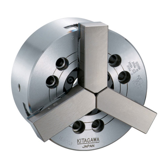
INSTRUCTION MANUAL
QB300
Quick Jaw-Change Chuck
DANGER
・ This instruction manual is for production engineers and maintenance
personnel in charge of operation of this product. When a beginner uses
this product, receive instructions from experienced personnel, the
distributor or our company.
・ Before installing, operating or maintaining this equipment, carefully
read this manual and the safety labels attached to the equipment.
Failure to follow these instructions and safety precautions could result
in serious injury, death, or property damage.
・ Store this manual near equipment for future reference.
・ If any questions related to safety arise about this manual, please
confirm them with the distributor or our company.
Kitagawa Corporation
77-1,Motomachi,Fuchu -shi,Hiroshima,726-8610,Japan
type
TEL +81-(0)847 -40-0561
FAX +81-(0)847-45-8911
Version 1.07 (2021.08.03)
Original instructions
Advertisement
Table of Contents

Subscribe to Our Youtube Channel
Related Manuals for Kitagawa QB300


Summary of Contents for Kitagawa QB300
- Page 1 Version 1.07 (2021.08.03) Original instructions INSTRUCTION MANUAL QB300 type Quick Jaw-Change Chuck DANGER ・ This instruction manual is for production engineers and maintenance personnel in charge of operation of this product. When a beginner uses this product, receive instructions from experienced personnel, the distributor or our company.
- Page 2 Preface This manual provides detailed information about how to safely and correctly use the power chuck (QB300 type) for a lathe. Before starting to use this power chuck, read this manual carefully and always follow the instructions and warnings in "Important Safety Precautions" and "Precautions for Use"...
- Page 3 The chuck and cylinder from Kitagawa Corporation should be used together. If you must use a part not made by Kitagawa, check with us or our distributor to be sure it is safe to do so. We will not be responsible for injury, death, damage or loss caused by use of a chuck or cylinder made by another company unless this use has been approved by Kitagawa or its distributor.
-
Page 4: Table Of Contents
Table of Contents 1. Structural Drawing and Parts List -----------------------------------------------------------------------5 1-1. Type display 1-2. Structural drawing 1-3. Scope of product 1-4. Parts list Important Safety Precautions ------------------------------------------------------------8 3. Specifications ----------------------------------------------------------------------------------------------16 3-1. Specifications 3-2. Relationship between gripping force and rotation speed 3-3. - Page 5 For Machine Tool Manufacturers (Chapter 9) 9. Attachment -------------------------------------------------------------------------------------------------46 9-1. Outline drawing of attachment 9-2. Manufacturing and attachment of draw pipe 9-3. Attachment of chuck 10. Other Information ----------------------------------------------------------------------------------------57 10-1. About standards and orders 10-2. Information about markings of product 10-3.
-
Page 6: Structural Drawing And Parts List
1. Structural Drawing and Parts List 1-1. Type display Type display as shown below Fig.1 1-2. Structural drawing Fig.2... -
Page 7: Scope Of Product
1-3. Scope of product This instruction manual is for the chuck part. Fig.3 ・ To prevent the work from flying, safe design, maintenance and erroneous action prevention of the hydraulic system to maintain the gripping force of the chuck is extremely important. Thoroughly read the “Important Safety Precautions”... -
Page 8: Parts List
1-4. Parts list Fig.4 Table 1 Part name Quantity No. Part name Quantity 1 Body 17 Jaw change handle 2 Wedge plunger 18 Set screw 3 Master jaw 19 Set screw 4 Soft jaw 20 Set screw 5 Plunger nut 21 Attaching bolt 6 Draw nut 22 Socket head cap screw... -
Page 9: Important Safety Precautions
Important Safety Precautions Important safety precautions are summarized below. Please read this section before first starting to use this product. Failure to follow the safety precautions below will result in ! DANGER serious injury or death. Turn off main power supply before attaching, inspecting or replacing chuck, and before adding oil. - Page 10 Important Safety Precautions Failure to follow the safety precautions below will result in ! DANGER serious injury or death. Do not allow the rotation speed of the chuck to exceed the maximum allowable speed limit. (Refer to pages 17-22) For All Users ・...
- Page 11 Important Safety Precautions Failure to follow the safety precautions below will result in ! DANGER serious injury or death. Keep the height of the jaw within the range specified in the gripping force limit table (Refer to page 21). If you must use a jaw taller than a standard soft jaw, use less than the input (piston thrust force, draw pipe drawing force) specified in the gripping force limit table.
- Page 12 Important Safety Precautions Failure to follow the safety precautions below will result in ! DANGER serious injury or death. Use of a chuck and cylinder that cannot be used together safely may cause the cylinder to break at high pressure resulting in the chuck and work flying out.
- Page 13 Important Safety Precautions Failure to follow the safety precautions below will result in ! DANGER serious injury or death. When changing or reversing jaws, use jaw change handle. (Refer to pages 23-24) For All Users If work-piece is clamped with master jaw and soft jaw not completely matched, there is a danger of...
- Page 14 Important Safety Precautions Failure to follow the safety precautions below will result in ! DANGER serious injury or death. Always tighten the bolts at the specified torque. If the torque is insufficient or excessive, the bolt will break, which is dangerous as the chuck or work will fly out.
- Page 15 Important Safety Precautions Failure to follow the safety precautions below will result in ! DANGER serious injury or death. Provide sufficient strength for the draw pipe (Refer to pages 48-49). Provide sufficient screw depth for the draw pipe. Firmly tighten the draw pipe. For Machine Tool Manufactures ・...
- Page 16 Important Safety Precautions Failure to follow the safety precautions below could ! WARNING result in serious injury or death. Do not modify the chuck in a way not permitted by the manufacturer. For All Users ・ It may not only break the chuck but the chuck and the work may fly out, which is dangerous.
-
Page 17: Specifications
3. Specifications 3-1. Specifications Table 2 Type QB306 QB308 QB310 QB312 Plunger stroke Jaw stroke (in diameter) 10.6 Allowable maximum input force (kgf) (2243) (3467) (4385) (5608) Maximum static gripping force (kgf) (5812) (8565) (11319) (14684) Allowable maximum 5500 4500 4000 3000 rotation speed... -
Page 18: Relationship Between Gripping Force And Rotation Speed
・ The attaching bolts of the soft jaw are tightened at the specified torque. (Refer to page ・ The numerical values are obtained with the Kitagawa gripping force meter . The gripping position of the gripping force meter is at a position 1/2 of the height of the soft jaw top surface (height from the chuck surface to the top surface of the jaw). - Page 19 ・ The numerical values are obtained by the Kitagawa gripping force meter. The gripping position of the gripping force meter is at a position 1/2 of the height of the soft jaw top surface (height from the chuck surface to the top surface of the jaw).
- Page 20 Kitagawa gripping force meter is required. Fig.6 ・ In the case of processing a considerably unbalanced work, lower the rotation speed.
- Page 21 3-3. Relationship between gripping part center height, static griping force and input force / Relationship between top jaw mass moment and gripping force loss If the gripping part center height of the used top jaw (dimension H in Fig. 7) is higher than the gripping part center height of the standard soft jaw, a large load is applied to the master jaw, T nut, jaw attaching bolts, etc.
- Page 22 Fig.8...
- Page 23 Analysis of the gripping force, input force and rotation speed using Fig. 8 is carried out as shown below. ・ For example, in the case of QB306 standard soft jaw (mass moment 75.9kg・mm), it cannot exceed 5500min (rpm), and the gripping force loss due to the centrifugal force at this rotation speed is 38kN (approx.
-
Page 24: Jaw Change And Reverse Turn
4. Jaw change and reverse turn 4-1. Handle operation 1. Insert the jaw change handle (accessory) into the hex part of shaft located on the chuck periphery of master jaw. 2. Turn the handle 45°CW. (The engagement between the stop pin and the soft jaw inside of master jaw is reversed.) At this time, the jaw change and reverse turn are possible. - Page 25 Fig.9 ・ When changing and reversely turning the jaw, be sure to use the jaw change handle. ・ Since hex part of the handle end is made in the special shape so that the handle will be inserted and removed only when the master jaw is completely engaged to the soft jaw (stop pin is extruded from master jaw top) Consequently, use only attached exclusive handle.
-
Page 26: Forming Soft Jaw
5. Forming Soft Jaw 5-1.Forming soft jaw ・ There are two soft jaw of the standard soft jaw and high soft jaw (semi-standard) per chuck size. Use proper jaw by considering the shape, size, material, face roughness and cutting conditions, etc. Regulation of soft jaw height ・... - Page 27 Soft jaw forming inhibition area ・ The figure shows the forming inhibition area of soft jaw. (Refer to Fig.11) If this area is cut, the jaw is broken, thus resulting in a danger of scattering the jaw or work-piece. Fig.11 Table 4 Type Type of soft jaw...
- Page 28 Regulation of gripping face shape ・ Form the jaw so that the jaw gripping part is the same as the gripping diameter of the gripping matters (Work-piece, jaw forming plug, ring). ・ The gripping face for the gripping maters is to be R-face in the same direction. Even if R-face is in the same direction, don’t grip the work-piece in the line remarkably touched.
- Page 29 ・ Check that the reference mark on the side of the No. 1 master jaw is within the range of the entire stroke as shown in Fig. 13. Full stroke the jaw at least once a day to check it before work or when supplying grease, etc. If it goes out of the range of appropriate stroke due to loosening of the draw nut, etc., the work may not be gripped, and this is dangerous as the work will fly out.
-
Page 30: Forming Soft Jaw With Outside Diameter Gripping
5-2. Forming soft jaw with outside diameter gripping 1. Preparation of the plug for forming ・ Prepare the plug for forming. The surface roughness of the plug outside diameter is to be approximately 6.3s, and make a shape with sufficient thickness which does not distort. - Page 31 5. Forming Process the gripping part (dimension φd’) of the work ・ in the state that the plug is kept gripped. The φd’ part is to be approximately the same diameter (H7) as the diameter of the gripping part of the work, and process to be surface roughness at 6s or less.
-
Page 32: Forming Soft Jaw With Inside Diameter Gripping
5-3. Forming soft jaw with inside diameter gripping 1. Preparation of the ring for forming ・ Prepare the ring for forming. The surface roughness of the ring inside diameter is to be approximately 6.3s, and make a shape with a sufficient thickness which does not distort. 2. - Page 33 5. Forming Process the gripping part (dimension φd’) of the work in ・ the state that the ring is kept gripped. The φd’ part is to be approximately the same diameter (H7) as the diameter of the gripping part of the work, and process to be surface roughness at 6s or less.
-
Page 34: Forming Method When You Use Forming Jig
5-4. Forming method when you use forming jig 1. Preparation of the jig for forming ・ Prepare the jig for forming. (There is a commercially available product.) ・ Attach the pin (Example 1) or the bolt and nut (Example 2) by dividing equally into 3 portions onto the ring shape plate. - Page 35 5. Forming ・ Process the gripping part (dimension φd’) of the work in the state that the jig for forming is kept gripped. The φd’ part is to be approximately the same diameter (H7) as the diameter of the gripping part of the work, and process to be surface roughness at 6s or less.
-
Page 36: Usage
6. Usage This product is a device to fix a work-piece when it is processed by the lathe machine or the rotary table. The rotary cylinder closes the jaw and fixes a work-piece so that it does not move during processing. -
Page 37: Precautions Related To Usage Of Jaw
6-3. Precautions related to usage of jaw ・ If a soft jaw other than one made by Kitagawa Corporation is used, the engagement will be inferior, and the master jaw will be deformed, the gripping precision will worsen, and the work will fly out due to gripping failure, which is dangerous. -
Page 38: Precautions Related To Processing
6-4. Precautions related to processing <1> Unbalance ・ In the case of processing largely unbalanced work, lower the rotation speed. The work will fly out and this is dangerous. ・ Vibrations are generated if there is unbalance owing to the work or the jig, etc. Vibration not only will impart a negative influence on the process precision but also the endurance of the chuck being remarkably shortened, and the chuck may break. -
Page 39: Attachment Of Locator And Jig
6-5. Attachment of locator and jig ・ In the case of attaching the locator and the jig on the chuck body surface, tap or drill a hole in the additional process range specified in Fig. 14. Fig.14 Table 6 Type A (mm) B (mm) C (mm) -
Page 40: Maintenance And Inspection
Table 7 Genuine Kitagawa genuine product CHUCK GREASE PRO product (Kitagawa distributor of each country) Kitagawa chuck grease Conventional product Molykote EP Grease TORAY Dow Corning (only inside Japan) Conventional Chuck EEZ grease Kitagawa-Northtech Inc. - Page 41 ・ To keep the chuck running in the best condition for a long time, adequate grease lubrication is necessary. Insufficient grease lubrication causes a drop in the gripping force, operation failure at low hydraulic pressure, drop in gripping precision, abnormal wearing, seizing, etc. The work will fly out due to a drop in the gripping force and this is dangerous.
-
Page 42: Disassembling
7-3. Disassembling Disassembling procedures Read the following disassembling procedures with reference to page 8. 1. Turn off the main power of the machine before starting work. 2. Remove the jaw ・ Remove the soft jaw [4], following the jaw change procedure in page 23. 3. - Page 43 Disassembling procedures of stud ASSY and stop pin Disassembling procedures of stud ASSY ・ Remove set screw [19] on the master jaw side and loosen stud ASSY from the master jaw. When reassembling, align the notch of stud ASSY before mounting it in the direction of the set screw [19].
- Page 44 ・ Disassemble and clean the chuck at least once every 6 months or every 100,000 strokes (once every 2 months or more for cutting cast metal). If cutting powder or other substances stagnate inside the chuck, it will lead to insufficient stroke and a drop in the gripping force, and this is dangerous as the work will fly out.
-
Page 45: Malfunction And Countermeasures
8. Malfunction and Countermeasures 8-1. In the case of malfunction Check the points specified in the table below and take the appropriate countermeasure. Table 8 Defective Cause Countermeasure The chuck inside will break. Disassemble and replace the broken part. The chuck does not The sliding surface is seized. -
Page 46: Where To Contact In The Case Of Malfunction
・ If the chuck failed due to a seizure or breakage, remove the chuck from the machine, following the disassembly steps in page 41. When the jaws and covers cannot be removed due to a blockage of workpiece, do not disassemble forcibly but please contact us or our agent. - Page 47 For Machine Tool Manufactures Following pages are described for machine tool manufacturers (personnel who attach a chuck to a machine). Please read following instruction carefully when you attach or detach a chuck to machine, and please sufficiently understand and follow the instructions for safe operation.
- Page 48 ・ Attach the manual switching valve at a position where it is easy to operate for the attaching equipment. ・ Install the hydraulic unit at a position where the drain hose is not kinked and the needle of the pressure gauge is easily read. ・...
- Page 49 9-2. Manufacturing and attachment of draw pipe 1. Production of draw pipe Determine the length of the draw pipe as shown below. Fig.16 Fig.17 Table 9 Type Cylinder d (f7) e Min f Max -0.025 QB306 S1246 M55×2 M55×2 A+41 -0.050 -0.030 QB308...
- Page 50 ・ Provide sufficient strength for the draw pipe. If the draw pipe is broken due to insufficiency of the strength, the gripping force will be lost instantly, which is dangerous as the work will fly out. ・ Keep the dimension e and the dimension f in Fig. 16 for the draw pipe and a material with the tensile strength 380MPa (38kgf/mm ) or more must be used.
- Page 51 ・ Use the bolts attached to the chuck, and do not use other bolts. However, if you must use other bolts not provided by Kitagawa, use bolts that have at least a strength classification of 12.9 (10.9 for M22 or more) and be sure they are long enough.
- Page 52 3. Production of back plate ・ Process the engagement diameter of the back plate after measuring the actual spindle. ・ Run-out of the back plate directly affects the process precision. The end surface run-out of the back plate, spigot joint diameter run-out must be 0.005 mm or less. ・...
- Page 53 ・ Use the bolts attached to the chuck, and do not use other bolts. However, if you must use other bolts not provided by Kitagawa, use bolts that have at least a strength classification of 12.9 (10.9 for M22 or more) and be sure they are long enough.
- Page 54 9-3. Attachment of chuck 1. Attaching the draw pipe to the cylinder ・ Apply adhesive onto the screw part of the draw pipe, and screw it into the piston rod of cylinder. At this time, refer to the instruction manual for the cylinder for tightening torque. ・...
- Page 55 ・ Use the bolts attached to the chuck, and do not use other bolts. However, if you must use other bolts not provided by Kitagawa, use bolts that have at least a strength classification of 12.9 (10.9 for M22 or more) and be sure they...
- Page 56 Table 13 Bolt size Tightening torque N・m N・m N・m N・m N・m N・m N・m N・m 5. Adjust the position of the wedge plunger ・ The appropriate position of the wedge plunger at the cylinder forward end is the position when the dimension A in Fig.20 becomes as shown in the table below. ・...
- Page 57 Table 14 Type QB306 QB308 QB310 QB312 A (mm) 20.5 22.5 6. Attach the cover and check the run-out of the chuck ・ Keep the periphery run-out and the end surface run-out of the chuck at 0.02mm T.I.R or less. ・...
- Page 58 10. Other information 10-1. About standards and orders This product is based on the following standards or orders. ・ Machinery directive:2006/42/EC Annex I ・ EN ISO 12100:2010 ・ EN1550:1997+A1:2008 10-2. Information about markings of product Fig.22...
- Page 59 10-3.About disposal Ultimate disposal of this product should be handled according to all national laws and regulations.
- Page 61 Supply of Machinery (Safety) Regulations 2008 Annex VII part B. Product : Standard chuck Model : QB300 series (Models QB306, QB308, QB310, QB312) Serial number : See original declaration Manufacturer : Kitagawa Corporation...
- Page 62 The products herein are controlled under Japanese Foreign Exchange and Foreign Trade Control Act. In the event of importing and/or exporting the products, you are obliged to consult KITAGAWA as well as your government for the related regul ation prior to any transaction.
Need help?
Do you have a question about the QB300 and is the answer not in the manual?
Questions and answers