Table of Contents
Advertisement
Quick Links
Advertisement
Table of Contents

Related Manuals for FLIR IM75-2


Summary of Contents for FLIR IM75-2
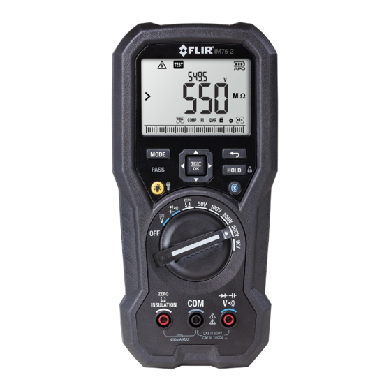
- Page 1 USER MANUAL FLIR MODEL IM75-2 Insulation Tester / Digital MultiMeter...
-
Page 2: Table Of Contents
5.4 ‘Smart’ Out-of-Range Warnings 5.5 Data Hold and Auto-Hold Modes 5.5.1 Data Hold Mode 5.5.2 Auto-Hold mode 5.6 Voltage Measurements 5.7 Insulation Resistance Measurements 5.7.1 PI/DAR Test 5.8 Earth Bond Resistance Measurements (ZERO Ω) FLIR IM75-2 USER MANUAL IM75-2-UM_en-US Rev AA... - Page 3 6.1 Cleaning and Storage 6.2 Battery Replacement 6.3 Fuse Replacement 6.4 Disposal of Electronic Waste SPECIFICATIONS 7.1 General specifications 7.2 Electrical Range Specifications 7.3 Input Specifications CUSTOMER SUPPORT WARRANTY 9.1 FLIR Limited Lifetime Warranty FLIR IM75-2 USER MANUAL IM75-2-UM_en-US Rev AA...
-
Page 4: Disclaimers
1. Disclaimers 1.1 Copyright © 2023, FLIR Systems, Inc. All rights reserved worldwide. No parts of the software including source code may be reproduced, transmitted, transcribed, or translated into any language or computer language in any form or by any means, electronic, magnetic, optical, manual, or otherwise, without the prior written permission of FLIR Systems. -
Page 5: Safety
Before operating the device, you must read, understand, and follow all instructions, dangers, warnings, cautions, and notes. FLIR Systems reserves the right to discontinue models, parts or accessories, and other items, or to • change specifications at any time without prior notice. -
Page 6: Fcc Compliance
Increase the separation between the equipment and receiver. Connect the equipment into an outlet on a circuit different from that to which the receiver is connected. Consult the dealer or an experienced radio/TV technician for help. FLIR IM75-2 USER MANUAL IM75-2-UM_en-US Rev AA... -
Page 7: Industry Canada Compliance
This device complies with Industry Canada license-exempt RSS standard(s). Operation is subject to the following two conditions: (1) this device may not cause interference, and (2) this device must accept any interference, including interference that may cause undesired operation of the device. FLIR IM75-2 USER MANUAL IM75-2-UM_en-US Rev AA... -
Page 8: Introduction
3. Introduction Thank you for selecting the FLIR IM75-2 Insulation Test / Digital MultiMeter. This device is shipped fully tested and calibrated and, with proper use, will provide years of reliable service. 3.1 Key Features • 4000 count extra-large digital dual display with backlighting Auto Range with smart over-range indication •... -
Page 9: Meter Description
COM (negative -) probe input jack Positive (+) probe input jack for insulation resistance and earth bond resistance Fig 4-1 Front View Courtesy Work Lights Test Probe Holders Tilt Stand Battery and Fuse Access Fig 4-2 Rear View FLIR IM75-2 USER MANUAL IM75-2-UM_en-US Rev AA... -
Page 10: Function Switch Positions
• Press this button to enable/disable the display backlight. • Press and hold the button for 2 seconds to enable/disable the work light. Press to enable/disable METERLiNK communication, see section 5.14 Streaming measurement data using METERLiNK. FLIR IM75-2 USER MANUAL IM75-2-UM_en-US Rev AA... -
Page 11: Selector Pad
• OFF: The meter is switched OFF. • AC/DC VOLTAGE: The meter can measure voltage through the probe inputs. The type of measurement (AC/DC) is chosen by the MODE button. The default measurement is AC voltage. FLIR IM75-2 USER MANUAL IM75-2-UM_en-US Rev AA... -
Page 12: Display Description
3. Bar graph (matches the reading on the main display) 4. Modes of operation (detailed later in this guide) 5. Units of measure for primary and secondary displays 6. Alerts and status icons (detailed below) FLIR IM75-2 USER MANUAL IM75-2-UM_en-US Rev AA... -
Page 13: Display Icons And Indicators
VFD (variable frequency drive) mode icon Frequency mode icon Earth Bond Resistance icon INSUL Insulation Resistance icon COMP Compare function icon Polarization Index icon Dielectric Absorption Ratio icon Settings mode icon Silent mode icon FLIR IM75-2 USER MANUAL IM75-2-UM_en-US Rev AA... -
Page 14: Operation
5.5.2 Auto-Hold mode If Auto-Hold mode is switched ON in the settings menu, press the HOLD button to activate Auto-Hold mode (the ‘H’ display icon will appear flashing). In Auto-Hold mode readings are FLIR IM75-2 USER MANUAL IM75-2-UM_en-US Rev AA... -
Page 15: Voltage Measurements
CLOCK icon and the elapsed time). PI is a ten-minute test and DAR is a one-minute test. The test will stop automatically, and the result (ratio) will be shown on the main display area. The PASS/FAIL LED will indicate the test result (Green for PASS, and Red for FAIL). FLIR IM75-2 USER MANUAL IM75-2-UM_en-US Rev AA... -
Page 16: Earth Bond Resistance Measurements (Zero Ω)
Warning: Do not do diode, resistance, or continuity tests before you have removed the power from capacitors and other devices under test during a measurement. Injury to persons can occur. 1. Set the function switch to the position. FLIR IM75-2 USER MANUAL IM75-2-UM_en-US Rev AA... -
Page 17: Capacitance Measurements
Fig 5-1 Mode Icons Use the left/right arrow buttons to navigate to the desired mode icon. The currently selected icon will flash. 1. Press the TEST OK button to enable the selected (flashing) mode. FLIR IM75-2 USER MANUAL IM75-2-UM_en-US Rev AA... -
Page 18: Vfd Mode (Acv Only)
Auto hold (indicated by the text A.Hold): Select Auto hold mode ON (Auto hold mode active) or OFF (Data hold mode active). For more information, see section 5.5 Data hold mode and Auto hold mode. FLIR IM75-2 USER MANUAL IM75-2-UM_en-US Rev AA... -
Page 19: Silent Mode
Press and hold the HOLD/LOCK button for 3 seconds to enter/exit the lockout mode. In lockout mode, the lock indicator is displayed. Do not confuse Lockout mode with the test lock feature used for continuous Insulation Resistance testing (see Section 5.7 Insulation Resistance Measurements). FLIR IM75-2 USER MANUAL IM75-2-UM_en-US Rev AA... -
Page 20: Streaming Measurement Data Using Meterlink
1. Download the METERLiNK app to your mobile device and open the app. 2. Power the meter and select the desired measurement mode. 3. Press the meter's Bluetooth button to enable communications. 4. Follow the instructions and prompts on the METERLiNK app screens FLIR IM75-2 USER MANUAL IM75-2-UM_en-US Rev AA... -
Page 21: Maintenance
As with most electronic products, this equipment must be disposed of in an environmentally friendly way, and in accordance with existing regulations for electronic waste. Please contact your FLIR Systems representative for more details. FLIR IM75-2 USER MANUAL IM75-2-UM_en-US Rev AA... -
Page 22: Specifications
TEST button. R1-min: The insulation resistance measured at the 1-minute point after pressing the TEST button. R30-sec: The insulation resistance measured at the 30 second point after pressing the TEST button FLIR IM75-2 USER MANUAL IM75-2-UM_en-US Rev AA... -
Page 23: Electrical Range Specifications
61 to 400Hz ± (5.0% + 5 digits) Notes: 1. Measurement start-voltage: <50V for VAC (add 20 digits for accuracy) 2. VFD/LPF Cutoff: 800Hz (-3dB point) 3. Input Impedance 10MΩ (less than 100pF) FLIR IM75-2 USER MANUAL IM75-2-UM_en-US Rev AA... - Page 24 Overload Protection: 1000V AC rms or DC Function Range Resolution Accuracy of Reading 1000 µF 1µF ± (1.2% + 2 digits) Capacitance 10.00mF 0.01mF ± (1.2% + 20 digits) Notes: 1. Overload Protection: 1000V AC rms or DC FLIR IM75-2 USER MANUAL IM75-2-UM_en-US Rev AA...
-
Page 25: Input Specifications
5. Live Circuit Detection: If >2V AC/DC detected test inhibited. The top LCD will display the actual live voltage sensed. 7.3 Input Specifications Function Maximum Input AC Voltage, DC Voltage 1000V DC/AC Insulation Test No LIVE Voltage IN - Protected FLIR IM75-2 USER MANUAL IM75-2-UM_en-US Rev AA... -
Page 26: Customer Support
8. Customer Support For technical assistance, repair and returns, document downloads, and general information, visit the support site, link below: https://support.flir.com FLIR IM75-2 USER MANUAL IM75-2-UM_en-US Rev AA... -
Page 27: Warranty
9. Warranty 9.1 FLIR Limited Lifetime Warranty This product is protected by FLIR’s Limited Lifetime Warranty. Visit https://support.flir.com/prodreg to register your product and read the Limited Lifetime Warranty document. FLIR IM75-2 USER MANUAL IM75-2-UM_en-US Rev AA... - Page 28 Specifications subject to change without further notice. Models and accessories subject to regional market considerations. License procedures may apply. Products described herein may be subject to US Export Regulations. Please refer to exportquestions@flir.com with any questions. There is no export-controlled information contained in this user manual.
Need help?
Do you have a question about the IM75-2 and is the answer not in the manual?
Questions and answers