Table of Contents
Advertisement
Quick Links
Advertisement
Table of Contents

Related Manuals for Johnson Controls SABROE HicaHP


Summary of Contents for Johnson Controls SABROE HicaHP
- Page 1 Operating manual Sabroe heat pump units HicaHP and NS HPAC...
- Page 3 Manual for Sabroe heat pump unit Refrigerant Other R717 Compressor type Compressor no. Condenser type Number of cassettes Evaporator type Number of cassettes Mechanical float valve HP control Electronic injection LP control Built into the condenser Oil cooling Water-cooled plate heat exchanger Ex-execution (ATEX) Both compressor and unit are safeguarded Operating manual - Sabroe heat pump units...
- Page 4 Vessel data Design pressure External surface Type [bar] Condenser Float housing Evaporator Liquid separator Oil separator Oil cooler Safety valve: Data for calculation of Receiver downstream line accord- ing to EN 13136 Economiser Desuperheater Subcooler Other Pressure loss, if any, from safety valve to customer connection (based on design pressure) [bar] _____________ Safety valve type: Back-pressure dependent...
-
Page 5: Table Of Contents
Contents Introduction ...................8 Introduction to manual ..............8 1.1.1 Amendments to the manual ...........9 1.1.2 Definition of safety precautions used in this manual ....10 1.1.3 Requirements for competent persons ........10 Safety ....................11 Areas of application ..............11 2.1.1 Application ................. - Page 6 3.2.8 LP regulating system (electrical) .......... 31 3.2.9 Subcooler ................32 3.2.10 Suction superheater ............32 3.2.11 Economiser ................ 33 3.2.12 Mechanical high-pressure float valve ........33 3.2.13 Intermediate cooler ............. 34 3.2.14 Automatic oil recovery system from evaporator ..... 34 3.2.15 Oil equalisation system ............
- Page 7 During operation ................ 48 5.4.1 Checks to be performed during operation ......48 5.4.2 Monitoring and logging of operation ........48 Stop procedures ................ 48 5.5.1 Stopping for a brief period ............ 48 5.5.2 Shutting down for a long standstill period ......48 Shutdowns and alarms ...............
-
Page 8: Introduction
It is important that the operating personnel familiarise themselves with the contents of this manual in order to ensure a proper and efficient operation. Johnson Controls Den- mark is not liable for damage occurring during the warranty period where this is attribut- able to incorrect operation. -
Page 9: Amendments To The Manual
Copyright © Johnson Controls Denmark This manual must not be copied without the written permission of Johnson Controls Denmark and the contents must not be imparted to a third party nor be used for any unauthorised purpo- ses. Contravention will be prosecuted. -
Page 10: Definition Of Safety Precautions Used In This Manual
Introduction 1.1.2 Definition of safety precautions used in this manual Danger! Indicates an imminently hazardous situation which, if not avoided, will result in death or serious injury. Warning! Indicates a potentially hazardous situation or practice which, if not avoided, will result in death or serious injury. -
Page 11: Safety
Warning! Johnson Controls Denmark is not liable for injuries to personnel or damage to equipment re- sulting from using the equipment for other purposes than the ones stated above. Operating manual - Sabroe heat pump units 009395 en 2023.02... -
Page 12: Identification
2.2.1 Identification of equipment All equipment from Johnson Controls Denmark can be identified by one or several name plates positioned as illustrated in the following drawings: Fig. 1: Identification of equipment - Sabroe heat pump unit seen from the front... - Page 13 Safety Fig. 2: Identification of equipment - Sabroe heat pump unit seen from the back Name plate for Pos. no. Compressor Vessel Compressor unit Piping system Evaporator Condenser Oil cooler Subcooler Suction superheater Operating manual - Sabroe heat pump units 009395 en 2023.02 13/68...
-
Page 14: Compressor Name Plates
Safety 2.2.2 Compressor name plates 1000010131 1000010132 Johnson Controls Denmark ApS Johnson Controls Denmark ApS Christian X's Vej 201 Christian X's Vej 201 8270 Højbjerg, Denmark 8270 Højbjerg, Denmark MADE IN DENMARK MADE IN DENMARK www.sabroe.com www.sabroe.com Serial Year Year... - Page 15 Safety The compressor name plate is positioned on the compressor and contains this information: Unique identification no. Serial no. Year of manufacturing. Year Type Manufacturer's type designation. Allowable refrigerant or refrigerants for the compressor. Refrigerant (The actual refrigerant for the unit is stated on the unit name plate).
-
Page 16: Vessel Name Plate
Allowable temperature, TS has been designed for. © Copyright - Johnson Controls Denmark ApS - All rights reserved. PROPRIE The volume of the vessel or vessel part. Volume The CE mark appears on the name plate for EC PED approval. -
Page 17: Unit/Pipe System Name Plate
Safety 2.2.4 Unit/pipe system name plate Johnson Controls Denmark ApS 1000010127 Johnson Controls Denmark ApS 1000010126 Christian X's Vej 201 Christian X's Vej 201 8270 Højbjerg, Denmark 8270 Højbjerg, Denmark MADE IN DENMARK MADE IN DENMARK www.sabroe.com www.sabroe.com Serial Serial... - Page 18 Safety The unit name plate is positioned on the frame and contains this information: Unique identification number. Serial No. Year of manufacturing. Year Type Manufacturer's type designation. For EC PED/EAC approval: ‘Unit & Piping’ means that the CE/ EAC mark applies to the complete unit including the piping sys- tem.
-
Page 19: Signs
Safety 2.2.5 Signs All signs which may be found on your equipment are shown below. The number of signs, how- ever, may vary from one product to another. High surface The compressor may be top- High voltage/ temperature Risk of electric shock High pressure heavy (about 70°C) -
Page 20: Safety Precautions
Safety Safety precautions 2.3.1 General precautions These precautions should be used as a supplement to the safety precautions and warnings in- cluded in: • All other manuals pertaining to the compressor/unit • Local, plant and shop safety rules and codes •... -
Page 21: Cooling Water Systems
Use the prescribed tools, and check that they are properly maintained and in good working condition. In explosion-proof areas, use tools suited for this specific purpose. • Use only Johnson Controls Denmark original spare parts; other parts may impair the safety of the compressor/unit. •... -
Page 22: Power Supply
Safety 2.3.6 Power supply Danger! • The voltage used in the drive can cause severe electric shock and/or burns and may be lethal. Extreme care must be taken at all times when working with or close to the drive. Specific warnings are given wherever relevant in this manual. •... -
Page 23: Purging A Refrigeration Plant
Safety 2.3.9 Purging a refrigeration plant Purging of air or other non-condensable gases is required in order to keep high system per- formance and avoid corrosion of the equipment, which could endanger the safety of persons and equipment. When purging a refrigeration system, make sure to observe the following: •... -
Page 24: First Aid For Accidents With Ammonia
Safety 2.3.10 First aid for accidents with ammonia (Chemical formula: NH , refrigerant no.: R717) General Ammonia is not a cumulative poison. It has a distinctive, pungent odour that even at very low, harmless concentrations is detectable by most people. As ammonia is self-alarming, it serves as its own warning agent so that no person stays volun- tarily in hazardous concentrations. -
Page 25: Protecting The Operator As Well As The Environment
Safety 2.3.11 Protecting the operator as well as the environment Industrialisation effects our environment and it is therefore essential that we do what we can to minimise the harmful effect on nature. Many countries have passed legislation in an effort to reduce pollution and preserve the envi- ronment. -
Page 26: Emergency Stop
Safety 2.3.12 Emergency stop In case of an accident, push the emergency stop button on the UniSAB III controller. Emergency stop Fig. 13: UniSAB III built into the electrical panel Emergency stop Fig. 14: UniSAB III as a separate device For resetting and further information, please see the UniSAB III manual. -
Page 27: Design And Function
The heat pump unit is a complete, factory-manufactured unit intended for heating of water and brine. Sabroe heat pumps delivered from Johnson Controls Denmark as a complete system must on- ly be used with ammonia (R717) as refrigerant. Once the unit is charged with R717, connected to electricity and pipe connections to water/brine are established, the heat pump is ready for operation. -
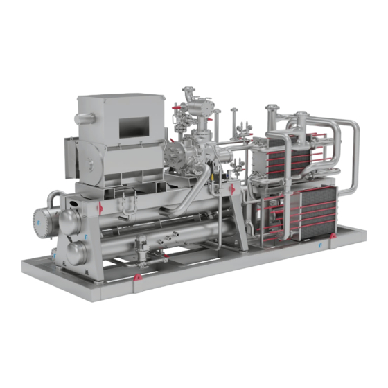
Page 28: Illustration Of A Sabroe Heat Pump Unit
Design and function 3.1.2 Illustration of a Sabroe heat pump unit Fig. 15: Sabroe heat pump unit with pos. numbers Pos. no. Component Evaporator Liquid separator Oil separator Condenser Subcooler Liquid receiver Compressor Motor Electrical panel UniSAB III/CHPPC Oil return system R717 charge valve Liquid level sensor Expansion valve... -
Page 29: Main Components
Design and function Main components 3.2.1 Compressor The compressor unit is a Johnson Controls Denmark standard unit, complete with oil separa- tor, oil return system, stop valves, motor, etc. The compressor operating manual contains a de- tailed description of this unit. 3.2.2... -
Page 30: Liquid Separator
Design and function The evaporator, pos. 1 in Fig. 16, is of the flooded type, which means that it is filled with boiling refrigerant (R717). This liquid leaves the liquid separator, pos. 2, and is led to the evaporator through the pipe, pos. 3. When the water or brine is cooled in the evaporator on its way through the connecting branches, pos. -
Page 31: Hp Regulating System (Electrical)
Design and function Fig. 18: Receiver 3.2.7 HP regulating system (electrical) Sabroe heat pump units are equipped with electrical regulation. The system is mounted on the outlet of the condenser and regulates the liquid level on the HP side. At the same time, the sys- tem controls the expansion between the LP and HP sides of the refrigeration plant. -
Page 32: Subcooler
Design and function Due to heavy boiling in the evaporator, the level in the level pipe is lower than the level in the evaporator, depending on the load. This must be taken into consideration when setting up the UniSAB III controller. To make sure the evaporator is not overcharged during standstill, a solenoid valve is fitted in front of the expansion valve. -
Page 33: Economiser
Design and function Sabroe suction superheaters are usually shell-and-tube heat exchangers, which are easy to implement in the suction line. 3.2.11 Economiser The economiser is made in different variations, for instance closed or open type. Fig. 20 illus- trates an open type. The liquid from the condenser is expanded into the open economiser through pos. -
Page 34: Intermediate Cooler
Design and function Fig. 21: Mechanical float valve 3.2.13 Intermediate cooler Sabroe two-stage heat pumps have an open intermediate cooler, Fig. 22, in the intermediate circuit. During operation, a mixture of vapour and liquid is expanded from the HP side and mixed with the discharge gas from the LP compressor. - Page 35 Design and function An oil recovery pot is connected to the evaporator by a sloping pipe. From the recovery pot, the oil is automatically returned to the compressor. Depending on the actual operating conditions, either a float or a liquid level sensor is fitted in the oil recovery pot, pos.
-
Page 36: Oil Equalisation System
Design and function Discharge gas is led into the oil reservoir through the small nozzle, pos. 2, Fig. 24. The rising pressure forces the oil back into the suction side of the compressor. To ensure proper functioning, a timer delays the off-signal from the float/liquid level switch for a few seconds. -
Page 37: Oil Level
Design and function Fig. 25: Oil equalisation between LP screw compressor and HP screw compressor For oil equalisation between an LP screw compressor and an HP reciprocating compressor: The oil return system returns oil to the screw compressor until an oil level switch in the HP re- ciprocating compressor is activated. -
Page 38: Purging The Refrigeration Plant
Design and function An equalisation line has been made to bypass the check valve in the compressor. In some cases, the equalisation can happen through the expansion valve. The equalisation pressure depends on the tightness of the valves and the volume of the LP and HP sides. If the equalisation happens rapidly, there is a risk of the pressure rising to a critical level, and the safety valve will lift and release pressure. -
Page 39: Installation Information
Installation information 4. Installation information Installation 4.1.1 General information For assistance or information about installation, please contact your local Johnson Controls product representative. 4.1.2 First start-up procedure Installation in terms of mechanical work (refrigeration system and piping), electrical work and installation of safety equipment must be performed in accordance with local codes/rules and/or according to EN 378-3 and EN 378-4 as a minimum requirement. -
Page 40: Sound And Vibrations
Installation information Evacuate the unit. 10. Charge oil if not charged from factory.* 11. Charge refrigerant. The P&I diagram states the charge for each specific heat pump. Start out by charging 75% of the specified R717 charge. The quality of the refrigerant must be appropriate for refrigeration applications. -
Page 41: Sound And Noise Data
Installation information 4.2.2 Sound and noise data Consult the compressor manual for sound and noise data. 4.2.3 Foundation To obtain the desired vibration damping, the concrete foundation must have the necessary bearing strength and be as plane as possible. Always collect weight information of the heat pump before projecting the concrete foundation. -
Page 42: Primary System
Installation information Primary system 4.3.1 R717 detector Installation of R717 detectors in the room and in the secondary circuit of an indirect system must be in accordance with EN 378 and/or local codes and rules. Detectors in the secondary circuit in indirect systems are recommended regardless of the R717 charge limit according to EN 378. -
Page 43: Secondary System
Installation information Secondary system 4.4.1 General information Designing a secondary system is a complex task where many things must be considered, for example: • load variations • pressure loss • service • maintenance • corrosion • fouling. Note: Rapid temperature variations in the secondary system can damage the heat pump unit. See subsection 4.4.2 below. -
Page 44: Temperature And Flow Control
It is therefore important to keep brine and water under observation for both evaporator and condenser. Consult a water treatment expert concerning additives to the system. The liability of Johnson Controls Denmark does not include any damage that may occur due to harmful im- purities in the system. - Page 45 Installation information Fig. 28: Lifting a Sabroe heat pump using two cranes Operating manual - Sabroe heat pump units 009395 en 2023.02 45/68...
-
Page 46: Operating Instructions
Operating instructions 5. Operating instructions Personnel qualification requirements Note: Read chapter 2. Safety carefully before operating the unit. Before operating the heat pump unit, all personnel must have studied the unit manuals carefully. The operator must be confident operating a UniSAB III controller. Prior to start-up and running of the heat pump, the pre-start check must be accomplished. -
Page 47: Starting
Operating instructions Starting 5.3.1 Starting procedures Starting and stopping can only be carried out from UniSAB III. The operator must always make sure that the appropriate external starting conditions exist before start-up. Top bar Content area Info bar F-key area Fig. -
Page 48: Restarting The Heat Pump After Alarm Stop (Shutdown)
Operating instructions 5.3.4 Restarting the heat pump after alarm stop (shutdown) Check and correct the cause of the alarm. Reset the alarm. UniSAB III should display: READY. Follow the normal start-up procedure. During operation 5.4.1 Checks to be performed during operation Choose a suitable picture from the UniSAB III display to view the data to be checked. -
Page 49: Shutdowns And Alarms
Operating instructions Turn of the oil heater. Close suction and discharge valves and all other valves connecting the plant. Rotate the motor and compressor (weekly/monthly according to below). To reduce the risk of bearing damage, it is recommended to rotate (to a new position) the motor and compressor on a monthly basis. - Page 50 Operating instructions Too low evaporating temperature Cause Solution Fouling in the evaporator Clean the evaporator. Oil in the evaporator Inspect the oil recovery system. Check liquid level in evaporator. Insufficient R717 charge Charge more R717 to the plant. Suction gas superheat should be approx. 5°K. A 1°K higher evaporating temperature results in a 4% higher cooling performance.
-
Page 51: Testing Of Heat Pump Units
5.6.3 Testing of heat pump units Sabroe heat pump units supplied by Johnson Controls Denmark have, as far as possible, been function and performance tested. A performance test consists of simultaneous measurements of cooling or heating capacity, power consumption and condenser capacity. -
Page 52: Maintenance Instructions
Maintenance instructions 6. Maintenance instructions Maintenance of heat pump units Read chapter 2. Safety carefully before performing any maintenance on the heat pump unit. To ensure that the heat pump unit operates without problems throughout a long service life, the system of maintenance presented in the following instructions must be followed. -
Page 53: Selecting Lubricating Oil For Heat Pump Units
Usually, the heat pump is charged with oil from factory. Do not switch to a different oil type or brand without first consulting Johnson Controls Denmark. Oil charges are described in detail in the compressor manual. For orders, see order-specific PID and GA drawings for oil type and charge. -
Page 54: Final Disposal
Final disposal 7. Final disposal Safety precautions Danger! Before dismantling the plant, read the safety precautions carefully. Dismantling a refrigeration unit to be scrapped must be carried out safely. Only competent refrigeration personnel must perform the dismantling as fundamental knowl- edge of refrigeration systems and the risks involved are required. -
Page 55: Appendices
Appendices 8. Appendices Monitoring of operation To ensure satisfactory operation, it is required that you enter certain routines in a logbook on a regular basis. You can use the items listed in the Start-up log, which is page 2 of the Checklist illustrated in Fig. -
Page 56: Set-Up Guide - Aks 4100 For Ammonia Heat Pump Application
Appendices Set-up guide - AKS 4100 for ammonia heat pump application Set-up guide for AKS 4100 Set-up and calibration of the AKS 4100 level sensor must be performed by competent person- nel only. The guide is in English only. Warning! Incorrect set-up may cause the compressor to break down. - Page 57 Appendices Open the tightening screw (pos. 1) on the meta glass connector and the fixing screw (pos. 2), see Fig. 31. Fit it carefully on the process connector. The loose screw (pos. 1) gives way for the trapped air so the signal converter can be installed. It should be pressed down carefully, yet with some force, to fit over the o-ring.
- Page 58 Appendices Check the settings You can check your settings by pressing twice. AKS 4100 COAX D22 280 mm (0%) 4 mA 210 mm 060 mm (100%) 20 mA Press to return to default screen. After running the quick set-up, go to the supervisor menu and change the following parameters: •...
- Page 59 Appendices Press Arrow up (no. 4) once to change the digit to 2. Press Arrow right (no. 1) again → passcode required → press the buttons: 1-2-3-4-1-2, see Fig. 35. Fig. 35 Example: how to change a parameter in the supervisor menu Change of gas constant 2.5.3 to value according to the list in .
- Page 60 Appendices • Press Arrow up (no. 4) until 1 has turned to 3, see Fig. 38. Fig. 38 Change the gas constant: • Press Arrow right (no. 1) – the bottom line is marked. • Change the digit to wanted number by pressing Arrow right (no. 1), Arrow down (no.
- Page 61 Appendices Change the following parameters in the same way: (AKS 4100 280 mm) • + 2.3.2 Blocking distance from 50 mm to 0 mm • + 2.3.3 Time constant from 5 sec. to 1 sec. • + 2.5.7 Level threshold from 200 mm to 150 mm •...
- Page 62 Appendices Danfoss Actual Settings Item Recommended values default values values Probe type Probe 800-1200- 280 mm 500 mm length 2200 mm 720-1120- 4 mA scale 210 mm 420 mm 2120 mm 20 mA scale 60 mm 120 mm 120 mm Blocking distance 0 mm...
- Page 63 Appendices Set point z on e Fig. 42: AKS 4100-280 mm installed in a DN150 receiver. Operating manual - Sabroe heat pump units 009395 en 2023.02 63/68...
- Page 64 Appendices Ref. plane Fig. 43: AKS 4100-500 mm installed in an LP ChillPAC DN50 standard pipe. Operating manual - Sabroe heat pump units 64/68 009395 en 2023.02...
- Page 65 Appendices Extended list – Gas constant for ammonia heat pump application R717 (NH Saturated vapour dielectric constant (default value: 1.066) Dielectric constant Temperature Pressure of refrigerant (°C) (bar) gas parameter -60 – -42 0.3 – 0.7 1.00 -41 – -18 0.7 –...
-
Page 66: Declaration Of Conformity
Appendices Declaration of conformity Johnson Controls Denmark declares on the signed declaration of conformity that the unit is manufactured and CE-marked in conformity with relevant directives and standards. The printed version of this operating manual, which is delivered with the unit, contains a trans- lated version of the declaration, however not filled in with the specific data for your unit. -
Page 67: Index
Index Amendments to the manual ......................Ammonia accidents - first aid ..................... Batteries ............................. Brine ............................Charge of R717 .......................... Cleaning in place........................Combustion engines - application....................Competent persons - requirements ................... Compressor..........................Compressor name plates ......................Condenser..........................Cooling media ..........................Cooling water systems ....................... - Page 68 Oil equalisation........................... Oil level............................Oil recovery, automatic....................... Oil types............................Operating instructions ........................ Operating log..........................Power supply..........................Pre-start............................Pressure equalisation......................... Purging ..........................23, 38 Refrigerants..........................Regulating system - HP ......................Regulating system - LP ......................Safety during maintenance and service..................Safety signs..........................Secondary sides.........................
- Page 70 Johnson Controls Denmark ApS Sabroe Factory Christian X's Vej 201 ∙ 8270 Højbjerg Denmark Phone +45 87 36 70 00 www.sabroe.com Version 4...
Need help?
Do you have a question about the SABROE HicaHP and is the answer not in the manual?
Questions and answers