Table of Contents
Advertisement
Quick Links
Advertisement
Table of Contents

Related Manuals for Supermicro X7DCL-3


Summary of Contents for Supermicro X7DCL-3
- Page 1 UPER X7DCL-3 X7DCL-i USER’S MANUAL Revision 1.0a...
- Page 2 Clara County in the State of California, USA. The State of California, County of Santa Clara shall be the exclusive venue for the resolution of any such disputes. Supermicro's total liability for all claims will not exceed the price paid for the hardware product.
-
Page 3: Manual Organization
These features allow the motherboard to operate at much higher speeds with lower power consumption in much safer thermal environments than the traditional motherboards. The X7DCL-3/X7DCL-i is ideal for complex business applications and servers. Please refer to the motherboard specifi cations pages on our web site (http://www.supermicro.com/products/motherboard/) for updates. -
Page 4: Table Of Contents
Conventions Used in the Manual ... iii Chapter 1: Introduction Overview ... 1-1 Checklist ... 1-1 Contacting Supermicro ... 1-2 X7DCL-3/i Image ... 1-3 X7DCL-3/i Layout ... 1-4 Quick Reference ... 1-5 Motherboard Features ... 1-6 Intel 5100 Chipset: System Block Diagram ... 1-8 Chipset Overview ... - Page 5 Power Button ... 2-13 Connecting Cables ... 2-14 ATX Power Connector ... 2-14 Processor Power Connector ... 2-14 Universal Serial Bus (USB) ... 2-15 Fan Headers ... 2-16 Chassis Intrusion ... 2-16 ATX PS/2 Keyboard and Mouse Ports ... 2-17 Serial Ports ...
- Page 6 X7DCL-3/X7DCL-i User's Manual Chapter 3: Troubleshooting Troubleshooting Procedures ... 3-1 Before Power On ... 3-1 No Power ... 3-1 No Video ... 3-1 Losing the System’s Setup Confi guration ... 3-1 Memory Errors ... 3-2 Technical Support Procedures ... 3-2 Frequently Asked Questions ...
-
Page 7: Chapter 1: Introduction
Checklist Congratulations on purchasing your computer motherboard from an acknowledged leader in the industry. Supermicro boards are designed with the utmost attention to detail to provide you with the highest standards in quality and performance. Check that the following items have all been included with your motherboard. If anything listed here is damaged or missing, contact your retailer. -
Page 8: Contacting Supermicro
X7DCL-3/X7DCL-i User's Manual Contacting Supermicro Headquarters Address: Super Micro Computer, Inc. 980 Rock Ave. San Jose, CA 95131 U.S.A. Tel: +1 (408) 503-8000 Fax: +1 (408) 503-8008 Email: marketing@supermicro.com (General Information) support@supermicro.com (Technical Support) Web Site: www.supermicro.com Europe Address: Super Micro Computer B.V. -
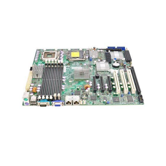
Page 9: X7Dcl-3/I Image
Chapter 1: Introduction X7DCL-3/X7DCL-i Image Note: The drawings and pictures shown in this manual were based on the latest PCB Revision available at the time of publishing of the manual. The motherboard you’ve received may or may not look exactly the same as the... - Page 10 4. When LED3 is on, make sure to unplug the power cable before removing or installing components. 5. All features and components related to SAS are available on the X7DCL-3 only, including SAS Connectors, the LSI SAS HostRAID Controller, and the I-Button socket.
-
Page 11: Quick Reference
Description LED1 SAS LED LED3/LED4 Power LED (LED3)/System Status LED (LED4) LED5/LED6 CPU1/CPU2 VRM Overheat (respectively) Note: SAS is available on the X7DCL-3 only. Default Setting See Chapter 2 Open (Disabled) Pins 1-2 (Enabled) Pins 1-2 (Enabled) Closed (Software RAID) -
Page 12: Motherboard Features
X7DCL-3/X7DCL-i User's Manual Motherboard Features • Dual Intel ® 64-bit Xeon LGA 771 Quad Core/Dual Core 5400/5300/5200/5100 Series processors at a front side bus speed of 1333 MHz/1066 MHz Memory • Six 240-pin DIMM sockets with support up to 32 GB Single-Rank, Registered/ ECC DDR2 667/533 Memory (See Section 2-3 in Chapter 2 for DIMM Slot Population.) - Page 13 • Six SATA ports support RAID 0, 1, 10 and 5 (in the Windows OS environ- ment) • Eight SAS ports supports RAID 0, 1, 10 and 5. (For X7DCL-3 only) • One SIMLC IPMI 2.0 socket • Intel 82573V and 82573L LAN chips support two Giga-bit LAN ports •...
- Page 14 X7DCL-3/X7DCL-i User's Manual ISL6312A PCI-EXP x8 PCI-EXP x8 PCI-EXP x8 3.0 Gb/S LSI 1068E PCI-EXP x1 RJ45 82573V PCI-EXP x1 RJ45 82573L DDR2 SDRAM 32MB PCI 33MHz Volari Z9S CONN IT8213F PCI-33 PCI-33 PCI-33 Block Diagram of the Intel 5100 Chipset Note: This is a general block diagram.
-
Page 15: Chipset And Processor Features Overview
Chipset and Processor Features Overview Built upon the functionality and the capability of the Intel 5100 chipset, the X7DCL- 3/X7DCL-i motherboard provides the performance and feature set required for dual processor-based high-end servers with confi guration options optimized for intensive computing, high energy-effi ciency and complex business applications. The 5100 chipset supports single or dual Intel Xeon 64-bit Quad Core/Dual Core 5400/5300/5200/5100 Series processors with front side bus speeds of up to 1.333 GHz. -
Page 16: Special Features
Advanced BIOS Setup section to change this setting. The default setting is Last State. PC Health Monitoring This section describes the PC health monitoring features of the X7DCL-3/X7DCL- i. All have an onboard System Hardware Monitor chip that supports PC health monitoring. -
Page 17: Acpi Features
System Resource Alert This feature is available when used with Supero Doctor III in the Windows OS environment or used with Supero Doctor II in Linux. Supero Doctor is used to notify the user of certain system events. For example, if the system is running low on virtual memory and there is insuffi... -
Page 18: Power Supply
It is even more important for processors that have high CPU clock rates. The X7DCL-3/X7DCL-i can only accommodate 24-pin ATX power supply. Although most power supplies generally meet the specifi cations required by the motherboard, some are inadequate. You should use one that will supply at least 400W of power. - Page 19 Chapter 1: Introduction K, 1.2 M, 1.44 M or 2.88 M disk drives and data transfer rates of 250 Kb/s, 500 Kb/s or 1 Mb/s. It also provides two high-speed, 16550 compatible serial communication ports (UARTs). Both UARTs provide legacy speed with baud rate of up to 115.2 Kbps as well as an advanced speed with baud rates of 250 K, 500 K, or 1 Mb/s, which support higher speed modems.
- Page 20 X7DCL-3/X7DCL-i User's Manual Notes 1-14...
-
Page 21: Chapter 2: Installation
Static-Sensitive Devices Electro-Static-Discharge (ESD) can damage electronic com ponents. To prevent damage to your system board, it is important to handle it very carefully. The fol- lowing measures are generally suffi cient to protect your equipment from ESD. Precautions • Use a grounded wrist strap designed to prevent static discharge. •... -
Page 22: Processor And Heatsink Fan Installation
X7DCL-3/X7DCL-i User's Manual Processor and Heatsink Fan Installation When handling the processor package, avoid placing direct pressure on the label area of the fan. Notes: • Always connect the power cord last and always remove it before adding, re- moving or changing any components. Make sure that you install the processor into the CPU socket before you install the CPU heatsink. - Page 23 Loading the Processor into the Socket Use your thumb and your index fi nger to hold the CPU at the North Center Edge and the South Center Edge of the CPU. Align CPU Pin1 (the CPU corner marked with a triangle) against the socket corner that is marked with a triangle cutout.
- Page 24 X7DCL-3/X7DCL-i User's Manual Installing the Heatsink Do not apply any thermal grease to the heatsink or the CPU die; the required amount has already been applied. Place the heatsink on top of the CPU so that the four mounting holes are aligned with those on the retention mechanism.
- Page 25 CPU and the heatsink. Mounting the Motherboard in the Chassis All motherboards have standard mounting holes to fi t different types of chassis. Make sure that the locations of all the mounting holes for both motherboard and chassis match. Make sure that the metal standoffs click in or are screwed in tightly.
-
Page 26: Installing Dimms
Repeat for all modules (See step 1 above.) Memory Support The X7DCL-3/X7DCL-i supports up to 32 GB Single-Rank, Registered ECC DDR2 667/533 in 6 DIMMs. Populating DIMM modules with pairs of memory modules of the same size and same type will result in Interleaved Memory which will improve memory performance. - Page 27 PCI Enumeration Area 2 (if needed) -Aligned on 256- MB boundary- VGA Memory TSEG Memory available to OS and other applications Figure 2-2. Installing and Removing DIMMs X7DCL-3/i To Remove: Use your thumbs to gently push the re- lease tabs near both ends of the module to release it from the slot.
-
Page 28: Control Panel Connectors And Io Ports
X7DCL-3/X7DCL-i User's Manual Control Panel Connectors/IO Ports The I/O ports are color coded in conformance with the PC 99 specifi cation. See Figure 2-3 below for the colors and locations of the various I/O ports. Back Panel Connectors/IO Ports X7DCL-3/i Back Panel I/O Port Locations and Defi... -
Page 29: Front Control Panel
Super Micro server chassis. See Figure 2-4 for the descriptions of the various control panel buttons and LED indicators. Refer to the following section for descriptions and pin defi nitions. JF1 Header Pins X7DCL-3/i Chapter 2: Installation Ground Power LED... -
Page 30: Front Control Panel Pin Defi Nitions
X7DCL-3/X7DCL-i User's Manual Front Control Panel Pin Defi nitions NMI Button The non-maskable interrupt button header is located on pins 19 and 20 of JF1. Refer to the table on the right for pin defi nitions. Power LED The Power LED connection is located on pins 15 and 16 of JF1. -
Page 31: Hdd Led
LED connection for GLAN Port2 is on Pins 9 and 10. Attach the NIC LED cables to display network activity. Refer to the table on the right for pin defi nitions. X7DCL-3/i Chapter 2: Installation HDD LED Pin Defi nitions (JF1) Pin# Defi... -
Page 32: Overheat/Fan Fail Led
X7DCL-3/X7DCL-i User's Manual Overheat/Fan Fail LED (OH) Connect an LED to the OH/Fan Fail connection on pins 7 and 8 of JF1 to provide advanced warnings of chassis overheating or fan failure. Refer to the table on the right for pin defi... -
Page 33: Reset Button
Chapter 4). To turn off the power when set to suspend mode, press the button for at least 4 seconds. Refer to the table on the right for pin defi nitions. X7DCL-3/i Chapter 2: Installation Reset Button Pin Defi nitions (JF1) Pin# Defi... -
Page 34: Connecting Cables
X7DCL-3/X7DCL-i User's Manual Connecting Cables ATX Power Connector A 24-pin main power supply connec- tor is located at JPW2, and an 8-pin CPU PWR connector is locatged at JPW1 on the motherboard. These power connectors meet the SSI EPS 12V specifi cation. See the table on the right for pin defi... -
Page 35: Universal Serial Bus (Usb)
JPWF1 SMB_PS 24-Pin PWR 8-Pin PWR DIMM2A DIMM1A DIMM2B DIMM1B DIMM2C DIMM1C X7DCL-3/i JPL2 CTRL Intel 5100 North Bridge I-Button CTRL Slot6 PCI-E x8 Buzzer Intel Slot5 PCI-E x8 ICH9R... -
Page 36: Fan Headers
X7DCL-3/X7DCL-i User's Manual Fan Headers The X7DCL-3/X7DCL-i has four chassis/ system fan headers (Fan3 to Fan6), and two CPU Fans (Fans 1/2). All these fans are 4-pin fans. However, Pins 1-3 of the fan headers are backward compatible with the traditional 3-pin fans. -
Page 37: Atx Ps/2 Keyboard And Mouse Ports
JCOM2. See the table on the right for pin defi nitions. JPWF1 SMB_PS 24-Pin PWR 8-Pin PWR DIMM2A DIMM1A DIMM2B DIMM1B DIMM2C DIMM1C X7DCL-3/i JPL2 CTRL Intel 5100 North Bridge I-Button CTRL Slot6 PCI-E x8 Buzzer Intel Slot5 PCI-E x8 ICH9R... -
Page 38: Wake-On-Ring
X7DCL-3/X7DCL-i User's Manual Wake-On-Ring The Wake-On-Ring header is lo- cated at JWOR1. This feature allows your computer to receive and be "awakened" by an incoming call to the modem when the system is in the suspend state. See the table on the right for pin defi... -
Page 39: Glan 1/2 (Ethernet) Ports
6-7 with a jumper. JPWF1 SMB_PS 24-Pin PWR 8-Pin PWR DIMM2A DIMM1A DIMM2B DIMM1B DIMM2C DIMM1C X7DCL-3/i JPL2 CTRL Intel 5100 North Bridge I-Button CTRL Slot6 PCI-E x8 Buzzer Intel Slot5 PCI-E x8 ICH9R... -
Page 40: Alarm Reset
X7DCL-3/X7DCL-i User's Manual Alarm Reset If three power supplies are installed, the system will notify you when any of the three power modules fails. Con- nect JAR1 to a micro-switch to turn off the alarm that is activated when a power module fails. -
Page 41: Vga Connector
SATA activities, J9 and J10 are used to monitor SAS connections. See the table on the right for pin defi nitions. Refer to the board layout below for the locations of the headers. (J9, J10: X7DCL-3 Only.) JPWF1 SMB_PS 24-Pin PWR 8-Pin PWR... -
Page 42: Power Smb (I 2 C)
X7DCL-3/X7DCL-i User's Manual Power SMB (I C) Connector Power SMB (I C) Connector (JPI monitors the status of the power supply, fan and system temperature. See the table on the right for pin defi nitions. BP PWR SMB (I C) Connector... -
Page 43: Keylock
"locking" it. JPWF1 SMB_PS 24-Pin PWR 8-Pin PWR DIMM2A DIMM1A DIMM2B DIMM1B DIMM2C DIMM1C X7DCL-3/i JPL2 CTRL Intel 5100 North Bridge I-Button CTRL Slot6 PCI-E x8 Buzzer Intel Slot5 PCI-E x8 ICH9R... -
Page 44: Jumper Settings
X7DCL-3/X7DCL-i User's Manual Jumper Settings Explanation of Jumpers To m o d i f y t h e o p e r a t i o n o f t h e motherboard, jumpers can be used to choose between optional settings. -
Page 45: Cmos Clear
Watch Dog must also be enabled in the BIOS. JPWF1 SMB_PS 24-Pin PWR 8-Pin PWR DIMM2A DIMM1A DIMM2B DIMM1B DIMM2C DIMM1C X7DCL-3/i JPL2 CTRL Intel 5100 North Bridge I-Button CTRL Slot6 PCI-E x8 Buzzer Intel Slot5 PCI-E x8 ICH9R... -
Page 46: Vga Enable/Disable
X7DCL-3/X7DCL-i User's Manual VGA Enable/Disable JPG1 allows you to enable or disable the VGA port. The default position is on pins 1 and 2 to enable VGA. See the table on the right for jumper settings. C Bus to PCI/PCI-Exp. Slots... -
Page 47: Sas Enable
RAID or IT RAID. Close this jumper to use Software RAID (Default). Set this jumper to open to use the IT RAID mode. Contact Tech. Support at Supermicro for more information. See the table on the right for jumper settings. -
Page 48: Onboard Led Indicators
X7DCL-3/X7DCL-i User's Manual Onboard LED Indicators GLAN LEDs There are two GLAN ports on the moth- erboard. Each Gigabit Ethernet LAN port has two LEDs. The yellow LED indicates activity, while the power LED may be green, orange or off to indicate the speed of the connection. -
Page 49: System Status Led
See the layout below for the LED locations. JPWF1 SMB_PS 24-Pin PWR 8-Pin PWR DIMM2A DIMM1A DIMM2B DIMM1B DIMM2C DIMM1C X7DCL-3/i JPL2 CTRL Intel 5100 North Bridge I-Button CTRL Slot6 PCI-E x8 Buzzer Intel Slot5 PCI-E x8 ICH9R South Bridge... - Page 50 A SAS LED is located at LED1 on the motherboard. This LED indicates the status of SAS connections. Refer to the table on the right for LED1 settings. See the layout below for the LED location. (Available on the X7DCL-3 only) JPWF1 SMB_PS 24-Pin PWR 8-Pin PWR...
-
Page 51: Floppy Connector
JFDD1. See the table below for pin defi nitions. JPWF1 SMB_PS 24-Pin PWR 8-Pin PWR DIMM2A DIMM1A DIMM2B DIMM1B DIMM2C DIMM1C X7DCL-3/i JPL2 CTRL Intel 5100 North Bridge I-Button CTRL Slot6 PCI-E x8 Buzzer Intel Slot5 PCI-E x8 ICH9R South Bridge... -
Page 52: Ide Connector
X7DCL-3/X7DCL-i User's Manual IDE Connector An IDE Connector is located at JIDE1 on the motherboard. This motherboard uses the ITE IT8213F Controller. An IDE Driver is required for the IDE drive to function properly. See the table on the right for pin defi nitions. -
Page 53: Chapter 3: Troubleshooting
Troubleshooting Troubleshooting Procedures Use the following procedures to troubleshoot your system. If you have followed all of the procedures below and still need assistance, refer to the ‘Technical Support Procedures’ and/or ‘Returning Merchandise for Service’ section(s) in this chapter. Note: Always disconnect the power cord before adding, changing or install- ing any hardware components. -
Page 54: Memory Errors
Question' (FAQ) sections in this chapter or see the FAQs on our web site (http:// www.supermicro.com/support/faqs/) before contacting Technical Support. BIOS upgrades can be downloaded from our web site at http://www.supermicro. com/support/bios/. If you still cannot resolve the problem, include the following information when contacting Super Micro for technical support: •... -
Page 55: Frequently Asked Questions
Question: What are the various types of memory that my motherboard can support? Answer: The X7DCL-3/X7DCL-i has six 240-pin DIMM slots that support Single- Rank, Registered ECC DDR2 667/533 SDRAM modules. It is strongly recom- mended that you do not mix memory modules of different speeds and sizes. (See Chapter 2 for detailed Information.) - Page 56 X7DCL-3/X7DCL-i User's Manual on the outside of the shipping carton, and mailed prepaid or hand-carried. Ship- ping and handling charges will be applied for all orders that must be mailed when service is complete. This warranty only covers normal consumer use and does not cover damage in- curred in shipping or from failure due to the alternation, misuse, abuse or improper maintenance of products.
-
Page 57: Chapter 4: Bios
Introduction This chapter describes the Phoenix BIOS™ Setup utility for the X7DCL-3/X7DCL-i. The Phoenix ROM BIOS is stored in a fl ash chip and can be easily upgraded using a fl oppy disk-based program. Note: Due to periodic changes to the BIOS, some settings may have been added or deleted and might not yet be recorded in this manual. -
Page 58: Running Setup
X7DCL-3/X7DCL-i User's Manual Running Setup Default settings are in bold text unless otherwise noted. The BIOS setup options described in this section are selected by choosing the ap- propriate text from the main BIOS Setup screen. All displayed text is described in this section, although the screen display is often all you need to understand how to set the options (see the next page). -
Page 59: Main Bios Setup Menu
Chapter 4: BIOS Main BIOS Setup Menu Main Setup Features System Time To set the system date and time, key in the correct information in the appropriate fi elds. Then press the <Enter> key to save the data. System Date Using the arrow keys, highlight the month, day and year fi... - Page 60 X7DCL-3/X7DCL-i User's Manual IDE Primary Master/Slave, SATA Port1, SATA Port2, SATA Port3 and SATA Port4 These settings allow the user to set the parameters of IDE Primary Master/Slave, SATA Port1 Master/Slave, SATA Port2 Master/Slave, SATA Port3 Master, and SATA Port4 Master slots. Hit <Enter> to activate the following sub-menu screen for detailed options of these items.
- Page 61 Chapter 4: BIOS CHS Format The following items will be displayed by the BIOS: TYPE: This item displays the type of IDE or SATA Device. Cylinders: This item indicates the status of Cylinders. Headers: This item indicates the number of headers. Sectors: This item displays the number of sectors.
- Page 62 X7DCL-3/X7DCL-i User's Manual Serial ATA This setting allows the user to enable or disable the function of the Serial ATA. The options are Disabled and Enabled. Native Mode Operation Select the native mode for ATA. The options are: Parallel ATA, Serial ATA, Both, and Auto.
-
Page 63: Advanced Setup
Chapter 4: BIOS Advanced Setup Choose Advanced from the Phoenix BIOS Setup Utility main menu with the arrow keys. You should see the following display. The items with a triangle beside them have sub menus that can be accessed by highlighting the item and pressing <Enter>. Boot Features Access the submenu to make changes to the following settings. - Page 64 X7DCL-3/X7DCL-i User's Manual Power Button Behavior If set to Instant-Off, the system will power off immediately as soon as the user hits the power button. If set to 4-sec., the system will power off when the user presses the power button for 4 seconds or longer. The options are instant-off and 4-sec override.
- Page 65 Chapter 4: BIOS Cache Base 0-512K If enabled, this feature will allow the data stored in the base memory area: block 0-512K to be cached (written) into a buffer, a storage area in the Static DROM (SDROM) or to be written into L1, L2 cache inside the CPU to speed up CPU operations.
- Page 66 X7DCL-3/X7DCL-i User's Manual PCI Confi guration Access the submenu to make changes to the following settings for PCI devices. Onboard GLAN-1/Onboard GLAN-2 (Gigabit- LAN) OPROM Confi gure Select Enabled to allow the system to boot from the GLAN-1 connection or the GLAN-2 connection.
- Page 67 Advanced Chipset Control Access the submenu to make changes to the following settings. Warning : Take Caution when changing the Advanced settings. An incorrect setup, a very high DRAM frequency or an incorrect DRAM timing may cause the system become unstable. When this occurs, reset the setting to the default setting.
- Page 68 X7DCL-3/X7DCL-i User's Manual Advanced Processor Options Access the submenu to make changes to the following settings. CPU Speed This is a display that indicates the speed of the installed processor. Frequency Ratio (Available if supported by the CPU.) The feature allows the user to set the internal frequency multiplier for the CPU.
- Page 69 Chapter 4: BIOS and restart the system for the change to take effect. Please refer to Intel’s web site for detailed information. Intel EIST Support (Available if supported by the CPU.) Select Enabled to use the Enhanced Intel SpeedStep Technology and allows the system to automatically adjust processor voltage and core frequency in an effort to reduce power consumption and heat dissipation.
- Page 70 X7DCL-3/X7DCL-i User's Manual Floppy Disk Controller This setting allows you to assign control of the fl oppy disk controller. The options are Enabled (user defi ned), Disabled, and Auto (BIOS and OS controlled). Base I/O Address This setting allows you to select the base I/O address for the Floppy port. The options are Primary and Secondary.
- Page 71 Chapter 4: BIOS Console Redirection Access the submenu to make changes to the following settings. COM Port Address This item allows you to specify which COM port to direct the remote console to: Onboard COM A or Onboard COM B. This setting can also be Disabled. BAUD Rate This item allows you to set the BAUD rate for the console redirection.
- Page 72 X7DCL-3/X7DCL-i User's Manual Hardware Monitor Logic CPU Temperature Threshold This option allows the user to set a CPU temperature threshold that will activate the alarm system when the CPU temperature reaches this pre-set temperature threshold. The hardcode default setting is 80 C.
- Page 73 IPMI (The option is available only when an IPMI card is installed in the system.) 0IP0M0000I Specification Version: Version. Firmware Version: This item displays the current Firmware Version. System Event Logging Select Enabled to enable IPMI Event Logging. When this function is set to Disabled, the system will continue to log events received via system interface.
- Page 74 X7DCL-3/X7DCL-i User's Manual OS Boot Watch Dog Set to Enabled to enable OS Boot Watch Dog. The options are Enabled and Disabled. Timer for Loading OS (Minutes) This feature allows the user to set the time value (in minutes) for the previous item: OS Boot Watch Dog by keying-in a desired number in the blank.
- Page 75 Chapter 4: BIOS Realtime Sensor Data This feature display information from motherboard sensors, such as temperatures, fan speeds and voltages of various components. 4-19...
- Page 76 X7DCL-3/X7DCL-i User's Manual Security Choose Security from the Phoenix BIOS Setup Utility main menu with the arrow keys. You should see the following display. Security setting options are displayed by highlighting the setting using the arrow keys and pressing <Enter>. All Security BIOS settings are described in this section.
- Page 77 Password on Boot This setting allows you to determine if a password is required for a user to enter the system at bootup. The options are Enabled (password required) and Disabled (password not required). Boot Choose Boot from the Phoenix BIOS Setup Utility main menu with the arrow keys. You should see the following display.
-
Page 78: Exit
X7DCL-3/X7DCL-i User's Manual Exit Choose Exit from the Phoenix BIOS Setup Utility main menu with the arrow keys. You should see the following display. All Exit BIOS settings are described in this section. Exit Saving Changes Highlight this item and hit <Enter> to save any changes you made and to exit the BIOS Setup utility. -
Page 79: Post Error Beep Codes
Appendix A: POST Error Beep Codes Appendix A POST Error Beep Codes This section lists POST (Power On Self Test) error beep codes for the Phoenix BIOS. POST error beep codes are divided into two categories: recoverable and terminal. This section lists Beep Codes for recoverable POST errors. Recoverable POST Error Beep Codes When a recoverable type of error occurs during POST, BIOS will display a POST code that describes the problem. - Page 80 X7DCL-3/X7DCL-i User's Manual Notes...
-
Page 81: Appendix B: Installing The Windows Os
South Bridge RAID Settings before you install the Windows OS and other software drivers. To confi gure RAID settings, please refer to RAID Confi guration User Guides posted on our website at www.supermicro.com/support/manuals. B-1 Installing the Windows XP/2000/2003 OS for... - Page 82 Windows XP/2000/2003 installation. After the Windows XP/2000/2003 OS Installation is completed, the system will automatically reboot. Insert the Supermicro Setup CD that came with your motherboard into the CD Drive during system boot, and the main screen will display.
- Page 83 After installing each item, you must re-boot the system before proceeding with the next item on the list. 2. The X7DCL-3 supports SAS RAID features. To confi gure the LSI SAS HostRAID, please refer to the LSI folder for the LSI SAS HostRAID Utility and documentation.
- Page 84 X7DCL-3/X7DCL-i User's Manual Confi guring Supero Doctor III The Supero Doctor III program is a Web-based management tool that supports remote management capability. It includes Remote and Local Management tools. The local management is called the SD III Client. The Supero Doctor III program included on the CDROM that came with your motherboard allows you to monitor the environment and operations of your system.
-
Page 85: Appendix C: Installing Other Software Programs And Drivers
Supero Doctor III Interface Display Screen-II (Remote Control) Note: SD III Software can be downloaded from our Web site at: ftp://ftp. supermicro.com/utility/Supero_Doctor_III/. You can also download SDIII User's Guide at: http://www.supermicro.com/PRODUCT/Manuals/SDIII/UserGuide.pdf. For the Linux OS, we will still recommend that you use Supero Doctor II. - Page 86 X7DCL-3/X7DCL-i User's Manual Notes...
Need help?
Do you have a question about the X7DCL-3 and is the answer not in the manual?
Questions and answers