Advertisement
Available languages
Available languages
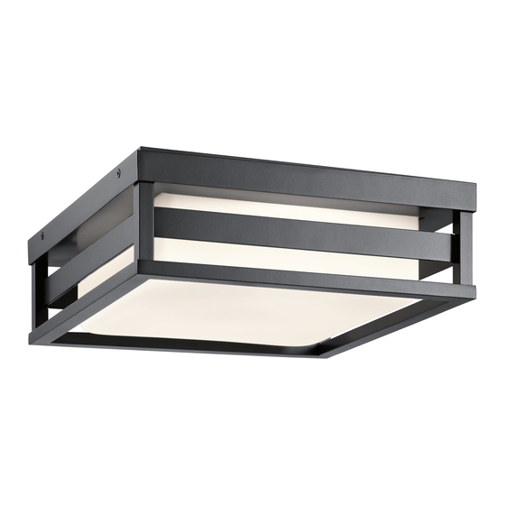
Fixture Diagram
G
Parts List
[A] Mounting
[D] Frame
Plate
[E] Plate
[B] Outlet Box
[C] Mounting
Screws
Cautions
CAUTION – RISK OF SHOCK –
Disconnect Power at the main circuit breaker panel or main
fusebox before starting and during the installation.
WARNING:
This fixture is intended for installation in accordance
with the National Electrical Code (NEC) and all local code
specifications. If you are not familiar with code requirements,
installation by a certified electrician is recommended.
CLEANING:
• Always be certain that electric current is turned off before
cleaning.
• Only a soft damp cloth should be used. Harsh cleaning
products may damage the finish.
Installation Instructions
1) Attach mounting plate[A] to outlet box[B] using the
plate mounting screws[E]. Mounting plate can be
adjusted to suit position of fixture.
2) Use the two (2) drywall anchors[F], one on each end
of the mounting plate, and secure with the two (2)
screws[H].
3) Grounding instructions: (See Illus. a or b).
a) On fixtures where mounting plate is provided with a
hole and two raised dimples, wrap ground wire from
outlet box around green ground screw, and thread
into hole.
b) On fixtures where a cupped washer is provided,
attach ground wire from outlet box under cupped
washer and green ground screw, and thread into
mounting plate.
FCC Information:
This device complies with part 15 of the FCC Rules. Operation is subject to the following two
conditions:
1)
This device may not cause harmful interference, and
2)
This device must accept any interference received, including interference that may cause
undesired operation.
Note: This equipment has been tested and found to comply with the limits for a Class B digital
device, pursuant to part 15 of the FCC Rules. These limits are designed to provide reasonable
protection against harmful interference in a residential installation. This equipment generates,
uses and can radiate radio frequency energy and, if not installed and used in accordance with
the instructions, may cause harmful interference to radio communications. However, there is
B
E
H
C
D
C
[F] Drywall
Anchors
Mounting
[G] Mounting
Screws
Pan
[H] Screws
Installation Instructions (continued)
If fixture is provided with ground wire, connect fixture
ground wire to outlet box ground wire with wire
connector after following the above steps. Never connect
F
ground wire to black or white power supply wires.
A
a
OUTLET BOX
GROUND
GREEN GROUND
SCREW
4) Make wire connections. Reference chart below for
correct connections and wire accordingly.
Connect Black or Red
Supply Wire to:
*Parallel cord (round &
smooth)
Clear, Brown, Gold or
Black without Tracer
Insulated wire (other
than green) with copper
conductor
*Note: When parallel wire (SPT
1 & SPT 2) are used. The neutral
wire is square shaped or ridged
and the other wire will be round
in shape or smooth (See illus.)
5) Raise mounting pan[G] to ceiling, carefully aligning the
mounting screw holes on the side of the mounting pan
with the holes on the side of the mounting plate[A].
6) Screw two (2) mounting screws[C] into aligned holes:
one on each side of the mounting pan.
7) Raise frame[D] up over mounting pan, carefully aligning
the mounting screw holes on the side of the frame with
the holes on the side of the mounting pan.
8) Screw four (4) mounting screws[C] into aligned holes:
two on each side of frame.
no guarantee that interference will not occur in a particular installation. If this equipment does
cause harmful interference to radio or television reception, which can be determined by turning
the equipment off and on, the user is encouraged to try to correct the interference by one or
more of the following measures:
•
Reorient or relocate the receiving antenna.
•
Increase the separation between the equipment and receiver.
•
Connect the equipment into an outlet on a circuit different from that to which the
receiver is connected.
•
Consult the dealer or an experienced radio/TV technician for help.
We're here to help
WIRE CONNECTOR
FIXTURE
GROUND
OUTLET BOX
DIMPLES
GROUND
GREEN GROUND
SCREW
Connect White Supply
Black
*Parallel cord (square &
Clear, Brown, Gold or Black
Insulated wire (other
than green) with silver
866-558-5706
Hrs: M-F 9am to 5pm EST
b
FIXTURE
GROUND
CUPPED
WASHER
Wire to:
White
ridged)
with Tracer
conductor
Neutral Wire
IS-59037LED-CB
Advertisement
Table of Contents

Subscribe to Our Youtube Channel
Related Manuals for Kichler Lighting Ryler 59037BKLED


Summary of Contents for Kichler Lighting Ryler 59037BKLED
- Page 1 866-558-5706 We’re here to help Hrs: M-F 9am to 5pm EST Fixture Diagram Installation Instructions (continued) If fixture is provided with ground wire, connect fixture ground wire to outlet box ground wire with wire connector after following the above steps. Never connect ground wire to black or white power supply wires.
- Page 2 INSTRUCTIONS: 866-558-5706 Nous sommes là pour vous aider For Assembling and Installing Fixtures in Canada Pour L’assemblage et L’installation Au Canada Heures : du lundi au vendredi, de 9h à 17h (heure de l’Est) Diagramme d’appareils Instructions d’installation 1) Fixer la plaque de montage[A] sur la boîte à prises[B] à...
- Page 3 866-558-5706 Estamos aquí para ayudarle Horario: Lunes-Viernes 9am a 5pm EST (hora oficial del este) Diagrama de Accesorios Instrucciones de Instalación (continuación) Si la lámpara viene con alambre a tierra, conecter el alambre a tierra de la lámpara al alambre a tierra de la caja tomacorriente con un conector de alambres espués de seguir los pasos anteriores.
Need help?
Do you have a question about the Ryler 59037BKLED and is the answer not in the manual?
Questions and answers