Table of Contents
Advertisement
Quick Links
Advertisement
Table of Contents

Related Manuals for SeaLevel ACB-104


Summary of Contents for SeaLevel ACB-104
- Page 1 ACB-104 User Manual | 3512 © Sealevel Systems, Inc. 3512 Manual | SL9125 9/2022...
-
Page 2: Table Of Contents
APPENDIX C – ELECTRICAL INTERFACE ......................19 APPENDIX D – DIRECT MEMORY ACCESS ...................... 21 APPENDIX E – ASYNCHRONOUS COMMUNICATIONS .................. 22 APPENDIX F – SILK SCREEN ..........................24 WARRANTY ................................ 25 © Sealevel Systems, Inc. 3512 Manual | SL9125 9/2022... -
Page 3: Introduction
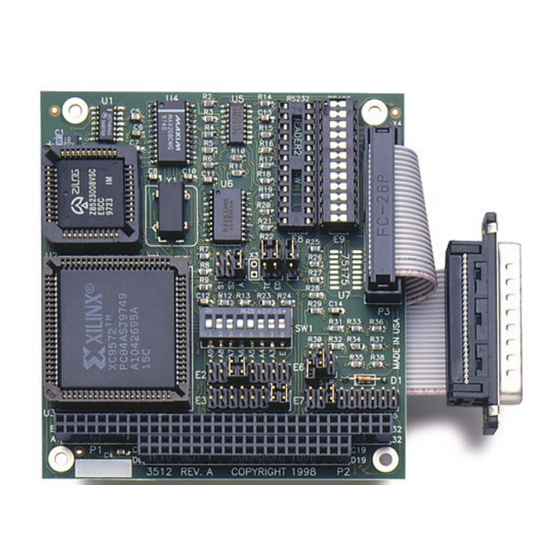
Overview The Sealevel Systems ACB-104 provides the PC with one high-speed RS-232/530/422/485 synchronous/asynchronous port. The ACB-104 can be used in a variety of sophisticated communications applications such as SDLC, HDLC, X.25, Bi-Sync, Mono-Sync, and high-speed asynchronous. © Sealevel Systems, Inc. -
Page 4: Before You Get Started
Before You Get Started What’s Included The ACB-104 is shipped with the following items. If any of these items are missing or damaged, contact the supplier. (1) ACB-104 Adapter • (1) DB-25 Cable Assembly • • (1) Nylon Hardware Kit... -
Page 5: Card Setup
The ACB-104 contains several jumper straps for each port, which must be set for proper operation. Port Enable Disable The ACB-104 can be enabled or disabled with switch position 8 on the DIP-switch. The port is enabled with the switch ‘On’ or ‘Closed’ and disabled when ‘Off’ or ‘Open’. - Page 6 Setting the switch ‘On’ or ‘Closed’ corresponds to a ‘0’ in the address, while leaving it ‘Off’ or ‘Open’ corresponds to a ‘1’. The relative I/O address of the ACB-104 registers are as follows: Base+0 Channel A Data Port •...
- Page 7 Electrical Interface Selection Headers E8 &E9 The ACB-104 has the ability to be used in either RS-232 or RS-530/422/485. This is selectable via two 24 pin DIP-shunts at E8 & E9. Please use the following illustration to aid in the configuration of your electrical interface.
- Page 8 Figure 4 - DMA Selection Headers E2 & E3 The DMA Channel 2 can only be used if the external DMA drivers are turned off. Please refer to the toolkit (available through Sealevel’s Technical support) for examples. DMA Jumper Option Tables...
- Page 9 DMA Channel 2 can only be used if the external DMA drivers are turned off. Please refer to the Toolkit available from Sealevel’s Technical Support for examples DMA Enable Header E1 Header E1 selects whether the DMA tri-state drivers are enabled permanently, (position A) disabled permanently (jumpers removed), or which DMA enable control port bit is used to enable the DMA hardware request and acknowledge signals.
-
Page 10: Installation
Only users running Windows 7 or newer should utilize these instructions for accessing and installing the appropriate driver via Sealevel’s website. If you are utilizing an operating system prior to Windows 7, please contact Sealevel by calling 864.843.4343 or emailing support@sealevel.com... - Page 11 Friday. For email support contact: support@sealevel.com. Physical Installation The ACB-104 can be installed in any of the PC expansion slots The ACB-104 contains several jumper straps for each port, which must be set for proper operation. 1. Turn off PC power. Disconnect the power cord.
-
Page 12: Technical Description
Programming the ACB-104 Control/Status Port The ACB-104 occupies eight input/output (I/O) addresses. The ESCC chip uses the first four, while the fifth address (Base+4) is the address of the on-board Control/Status Port. This port is used to set the Data Terminal Ready (DTR) and to enable or disable DMA under program control, and to monitor the Data Set Ready (DSR) input signals from the modem. - Page 13 In (Base+4), Mask=0000 0001 DMA Terminal Count The ACB-104 can be setup to operate using a polling method, interrupts, or system DMA. The most efficient method is a combination of DMA and interrupts. The ACB-104 has been optimized to generate an interrupt at the end of a DMA transfer.
- Page 14 RTS to CTS and RI. Also, connect DCD to DTR and DSR. Terminating these pins, if not used, will help insure you get the best performance from your adapter. © Sealevel Systems, Inc. 3512 Manual | SL9125...
- Page 15 The RS-530 specification calls for a 100-ohm 1/2-watt resistor between the signal ground and the chassis ground. On the IBM PC, these two grounds are already connected together, therefore this resistor is omitted. © Sealevel Systems, Inc. 3512 Manual | SL9125...
-
Page 16: Specifications
Board length 3.75 inches (9.54 cm) Board height including Goldfingers 3.5 inches (8.89 cm) Board height excluding Goldfingers 3.2 inches (8.12 cm) Please see Appendix F for board layout and dimensions. © Sealevel Systems, Inc. 3512 Manual | SL9125 9/2022... -
Page 17: Appendix A - Troubleshooting
Appendix A – Troubleshooting An ACB Developers Toolkit can be provided by Sealevel’s Technical Support team which may assist you in troubleshooting any issues you may be having. Please contact Technical Support as stated below. By using the toolkit and following these simple steps, most common problems can be eliminated without the need to call Technical Support. -
Page 18: Appendix B - How To Get Assistance
If possible, please have the adapter installed in a computer ready to run diagnostics. 3. Sealevel Systems provides an FAQ section on its web site. Please refer to this to answer many common questions. This section can be found at http://www.sealevel.com/faq.asp. -
Page 19: Appendix C - Electrical Interface
The RS-530 specification defines two types of interface circuits, Data Terminal Equipment (DTE) and Data Circuit-Terminating Equipment (DCE). The Sealevel Systems adapter is a DTE interface. RS-449 RS-449 (a.k.a. - Page 20 (Tx+ to Rx+ and Tx- to Rx-). Four wire mode allows full duplex data transfers. RS-485 does not define a connector pin-out or a set of modem control signals. RS-485 does not define a physical connector. © Sealevel Systems, Inc. 3512 Manual | SL9125 9/2022...
-
Page 21: Appendix D - Direct Memory Access
Memory to I/O or I/O to Memory transfer. When the data transfer is started, an acknowledge signal (DACK) is sent by the DMA controller chip to the ACB-104. Once the data has been transferred to or from the ACB-104 the DMA controller returns control to the Microprocessor. -
Page 22: Appendix E - Asynchronous Communications
The communication parameters are baud rate, parity, number of data bits per character, and stop bits (i.e.,9600,N,8,1). © Sealevel Systems, Inc. 3512 Manual | SL9125 9/2022... - Page 23 The actual sync flag and protocol varies depending on the sync format (SDLC, BISYNC, etc.). For a detailed explanation of serial communications, please refer to the book Technical Aspects of Data Communications by John E. McNamara, published by Digital Press (DEC) 1982. © Sealevel Systems, Inc. 3512 Manual | SL9125 9/2022...
-
Page 24: Appendix F - Silk Screen
Appendix F – Silk Screen 3.550" 3.775" © Sealevel Systems, Inc. 3512 Manual | SL9125 9/2022... -
Page 25: Warranty
Sealevel's commitment to providing the best I/O solutions is reflected in the Lifetime Warranty that is standard on all Sealevel manufactured I/O products. We are able to offer this warranty due to our control of manufacturing quality and the historically high reliability of our products in the field. Sealevel products are designed and manufactured at its Liberty, South Carolina facility, allowing direct control over product development, production, burn-in and testing.
Need help?
Do you have a question about the ACB-104 and is the answer not in the manual?
Questions and answers