
Related Manuals for SeaLevel ACB-II/EX


Summary of Contents for SeaLevel ACB-II/EX
- Page 1 ACB-II / EX User Manual | 4061 © Sealevel Systems, Inc. 4061 Manual | SL9164 11/2021...
-
Page 2: Table Of Contents
APPENDIX E – ASYNCHRONOUS AND SYNCHRONOUS COMMUNICATIONS ..................... 23 APPENDIX F – ACB DEVELOPER TOOLKIT AND ACB RESOURCE KIT ........................25 APPENDIX G – SILK SCREEN ......................................26 APPENDIX H – COMPLIANCE NOTICES ..................................27 WARRANTY ............................................28 © Sealevel Systems, Inc. 4061 Manual | SL9164 11/2021... -
Page 3: Introduction
Introduction Overview The Sealevel Systems ACB-II/EX provides the PC with one high-speed RS-232/530/422/485 synchronous/asynchronous ports. The ACB-II/EX can be used in a variety of sophisticated communications applications such as SDLC, HDLC, X.25, Bi-Sync, Mono-Sync, and high-speed asynchronous. © Sealevel Systems, Inc. -
Page 4: Before You Get Started
Before You Get Started What’s Included The ACB-II/EX is shipped with the following items. If any of these items are missing or damaged, contact the supplier. • ACB-II/EX Serial Interface Adapter Advisory Conventions Warning The highest level of importance used to stress a condition where damage could result to the product, or the user could suffer serious injury. - Page 5 Base Address DMA Selection Electrical Specification TX: 1 / RX: 3 RS-530/422 To install the ACB-II/EX using factory default settings, refer to the section on Installation. For your reference, record installed ACB-II/EX settings below: Base Address DMA Selection Electrical Specification ©...
-
Page 6: Card Setup
The ACB-II/EX contains several jumper straps for each port, which must be set for proper operation. Port Enable Disable The ACB-II/EX can be enabled or disabled with switch position 8 on the DIP-switch. The port is enabled with the switch ‘On’ or ‘Closed’ and disabled when ‘Off’ or ‘Open.’... - Page 7 Card Setup, Continued The relative I/O address of the ACB-II/EX registers are as follows: • Base+0 Channel A Data Port • Base+1 Channel A Control Port • Base+2 Channel B Data Port • Base+3 Channel B Control Port • Base+4 Board Control / Status Port •...
- Page 8 Electrical Interface Selection Headers E8 & E9 The ACB-II/EX has the ability to be used in either RS-232 or RS-530/422/485. This is selectable via two 24 pin DIP-shunts at E8 & E9. Please use the following illustration to aid in the configuration of your electrical interface.
- Page 9 Card Setup, Continued DMA Channel 2 can only be used if the DMA drivers in the software are turned off. Please refer to the toolkit available at Sealevel Systems for software examples. Please contact Technical Support for more information: support@sealevel.com.
- Page 10 Selects Always Enable Please refer to Section 4 for software bit definitions and examples of DMA driver control. When using Sealevel Software always select position A for “DMA Always Enabled.” IRQ Selection Header E6 Header E6 selects the interrupt request (IRQ) line for the card. If no interrupt is desired, remove the jumper.
- Page 11 Position ‘T’ on E5 enables the DMA Terminal Count Interrupt. Setting this jumper allows the selected DMA channel to generate an interrupt once the DMA Terminal Count has been reached. See Section 4 for the status bit (TC STAT) position and refer to the toolkit available at Sealevel Systems Technical Support for software examples.
-
Page 12: Installation
Installation Hardware Installation The ACB-II/EX can be installed in any of the PC expansion slots The ACB-II/EX contains several jumper straps for each port, which must be set for proper operation. Turn off PC power. Disconnect the power cord. Remove the PC case cover. - Page 13 The SeaMAC software for the ACB-II/EX is available upon request. For additional software support, please call Sealevel Systems’ Technical Support, (864) 843-4343. Our technical support is free and available from 8:00AM-5:00PM Eastern Time, Monday through Friday. For email support contact: support@sealevel.com.
-
Page 14: Technical Description
Programming the ACB-II/EX Control/Status Port The ACB-II/EX occupies eight input/output (I/O) addresses. The ESCC chip uses the first four, while the fifth address (Base+4) is the address of the on-board Control/Status Port. This port is used to set the Data Terminal Ready (DTR) and to enable or disable DMA under program control, and to monitor the Data Set Ready (DSR) input signals from the modem. - Page 15 In (Base+4), Mask=0000 0001 DMA Terminal Count The ACB-II/EX can be setup to operate using a polling method, interrupts, or system DMA. The most efficient method is a combination of DMA and interrupts. The ACB-II/EX has been optimized to generate an interrupt at the end of a DMA transfer.
- Page 16 RTS to CTS and RI. Also, connect DCD to DTR and DSR. Terminating these pins, if not used, will help insure you get the best performance from your adapter. © Sealevel Systems, Inc. 4061 Manual | SL9164 11/2021...
-
Page 17: Specifications
Non-Condensing Non-Condensing Manufacturing All Sealevel Systems Printed Circuit boards are built to UL 94V0 rating and are 100% electrically tested. These printed circuit boards are solder mask over bare copper or solder mask over tin nickel. Power Consumption Supply line... -
Page 18: Appendix A - Troubleshooting
No two adapters can occupy the same I/O address. 3. Make sure the Sealevel Systems adapter is using a unique IRQ. The IRQ is typically selected via an on-board header block. Refer to the section on Card Setup for help in choosing an I/O address and IRQ. -
Page 19: Appendix B - How To Get Assistance
If possible, please have the adapter installed in a computer ready to run diagnostics. Sealevel Systems provides an FAQ section on its web site. Please refer to this to answer many common questions. This section can be found at http://www.sealevel.com/faq.asp. -
Page 20: Appendix C - Electrical Interface
0 (space) and -12 volts (-3 to -10 volts) denotes a binary 1 (mark). The RS-232 and the EIA/TIA-574 specification defines two type of interface circuits, Data Terminal Equipment (DTE) and Data Circuit-Terminating Equipment (DCE). The Sealevel Systems adapter is a DTE interface. RS-422 The RS-422 specification defines the electrical characteristics of balanced voltage digital interface circuits. - Page 21 (Tx+ to Rx+ and Tx- to Rx-). Four wire mode allows full duplex data transfers. RS-485 does not define a connector pin-out or a set of modem control signals. RS-485 does not define a physical connector. © Sealevel Systems, Inc. 4061 Manual | SL9164 11/2021...
-
Page 22: Appendix D - Direct Memory Access
ACB-II/EX, the DMA controller returns control to the Microprocessor. To use DMA with the ACB-II/EX requires a thorough understanding of the PC DMA functions . The use of DMA with several source code and high level language demo programs. Please refer to the SCC User’s Manual for more information. -
Page 23: Appendix E - Asynchronous And Synchronous Communications
The communication parameters are baud rate, parity, number of data bits per character, and stop bits (i.e., 9600, N,8,1). © Sealevel Systems, Inc. 4061 Manual | SL9164 11/2021... - Page 24 (either another sync flag or a bit combination that signals the end of the text, e.g., EOT). The actual sync flag and protocol varies depending on the sync format (SDLC, BISYNC, etc.). © Sealevel Systems, Inc. 4061 Manual | SL9164 11/2021...
-
Page 25: Appendix F - Acb Developer Toolkit And Acb Resource Kit
ACB family. The ACB Resource Kit provides a brief overview of the ACB product line and is available at your request. For additional information, please contact Sealevel Systems, Inc. Technical Support for assistance: Available Monday – Friday, 8:00AM to 5:00PM EST... -
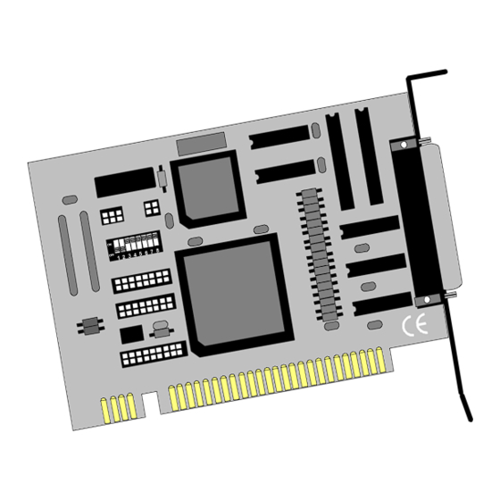
Page 26: Appendix G - Silk Screen
Appendix G – Silk Screen © Sealevel Systems, Inc. 4061 Manual | SL9164 11/2021... -
Page 27: Appendix H - Compliance Notices
Always use cabling provided with this product if possible. If no cable is provided or if an alternate cable is required, use high quality shielded cabling to maintain compliance with FCC/EMC directives. © Sealevel Systems, Inc. 8004 Manual | SL9022 9/2021... -
Page 28: Warranty
Sealevel's commitment to providing the best I/O solutions is reflected in the Lifetime Warranty that is standard on all Sealevel manufactured I/O products. We are able to offer this warranty due to our control of manufacturing quality and the historically high reliability of our products in the field. Sealevel products are designed and manufactured at its Liberty, South Carolina facility, allowing direct control over product development, production, burn-in and testing.
Need help?
Do you have a question about the ACB-II/EX and is the answer not in the manual?
Questions and answers