Advertisement
Quick Links
Advertisement

Related Manuals for Allen-Bradley PanelView 1200


Summary of Contents for Allen-Bradley PanelView 1200
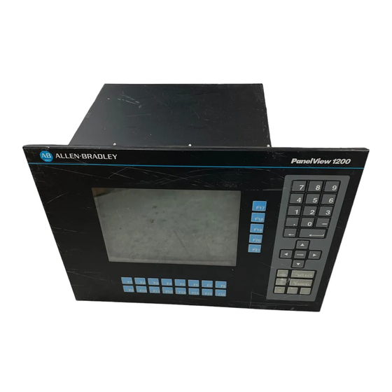
- Page 1 PanelView 1200 Operator Terminals (Catalog Numbers 2711-KA1, KC1, TA1, TC1, TA4, TC4) User Manual...
- Page 2 In no event will the Allen-Bradley Company be responsible or liable for indirect or consequential damages resulting from the use or application of this equipment.
- Page 3 ........Introduction to PanelView 1200 Operator Terminals...
- Page 4 Table of Contents PanelView 1200 Terminal Functions ....
- Page 5 Table of Contents Installing Your PanelView 1200 Terminal ....Verifying the PanelView 1200 Terminal Operation ..Maintaining Your PanelView 1200 Terminal...
- Page 6 Table of Contents Specifications ........Troubleshooting ....... .
- Page 7 1200 Configuration Software for Windows, and then saved in an application file on the development computer’s disk. The application file is then downloaded to a PanelView 1200 terminal where it stays in battery-backed RAM. Battery-Backed RAM: Application files are stored in the PanelView 1200 terminal’s random access memory (RAM).
- Page 8 Hex Files: Application files which have been converted into Intel format for transfer to user PROMs. Object: An object is an individual component of a PanelView 1200 screen. Each object takes the function of a button, switch or indicator on a control panel.
- Page 9 Preface There are two types of user PROM chips that can be used in PanelView 1200 terminal: EPROMs and EEPROMs. EPROMs are Electrically Programmable Read Only Memory chips. EEPROMs are Electrically Erasable Programmable Read Only Memory chips. The user PROMs store application files in memory that is protected from power failure and failure of the internal battery.
- Page 10 To identify the manuals referring to these programmable controllers, consult the Publications Index, Publication SD499, available from Allen-Bradley. After Sales Support If you need help with your PanelView 1200 terminal, contact: Allen-Bradley Global Technical Support 6680 Beta Drive Mayfield Village, Ohio 44143...
- Page 11 Chapter Introduction to PanelView 1200 Operator Terminals This chapter provides an overview of the PanelView 1200 terminals. It describes: the types and features of PanelView 1200 terminals the available options and accessories the supported Allen-Bradley programmable controllers and remote I/O...
- Page 12 Chapter 1 Product Description Catalog Number...
- Page 13 Panel or 19" Rack Mounting All PanelView 1200 terminals can be panel or 19” rack-mounted. Keypad and stud-mounted touch screen terminals are rated NEMA 4X (Indoor use only). Clip-mounted touch screen terminals are rated NEMA 12.
- Page 14 PLC system capable of supporting the Allen-Bradley 1771 Remote I/O Link. A PanelView 1200 terminal appears as one or more PLC I/O racks on an Allen-Bradley PLC Remote I/O link; it can be configured as up to 8 different racks—or fractional racks—with any valid PLC rack numbers.
- Page 15 Message and Alarm Handling Utilities A PanelView 1200 terminal application can be set up with stored messages that can be triggered by the PLC controller. There are three kinds of...
- Page 16 Built in Clock The battery-backed clock runs even when the terminal is powered down. PanelView 1200 can display the current time and date and can send it to the PLC controller. The clock may also be set by the PLC controller.
- Page 17 Chapter 1 PanelView 1200 Terminal Diagnostics When a PanelView 1200 terminal starts up, it performs a number of fault detection tests. The PanelView 1200 terminal also performs continuous tests for fault conditions when it is communicating online with the PLC controller.
- Page 18 PanelBuilder 1200 Configuration Software for Windows User Manual, or your PanelBuilder Development Software User Manual. foreground and background colors can be assigned only for color PanelView 1200 terminals. Inverse video and intensity settings are assigned for monochrome terminals Keypad Terminals...
- Page 19 Chapter 1 You can also configure the terminal to beep when a key is pressed. Figure 1.1 Keypad Terminal PanelView 21000 Function Keys When creating screens, you can assign any of the 21 function keys to objects so that they can perform a wide variety of functions, ranging from turning on PLC input bits to changing screens.
- Page 20 Chapter 1 Special Keys There are a series of special keys on the keypad terminal: the arrow keys are used with the Set Bit and Numeric Cursor Points and the ASCII Input object Home, Select work with the Set Bit and Numeric Input Cursor Points Cancel is designed to be used with all numeric keypads, Numeric Input and Set Bit Cursor Points.
- Page 21 Chapter 1 The touch screen terminal contains 120 touch cells. Each touch cell is 2 characters high by 8 characters wide. You can configure the terminal to beep when a touch cell is pressed. 20002 Touch cells are grouped to create different types and sizes of buttons. The following figure illustrates a single touch cell ON button with double height and double width characters, and a solid border.
- Page 22 Chapter 1 Table 1.C Objects for PanelView 1200 Terminals Object Type Keypad or Touch Screen terminal 1-12...
- Page 23 Latched Input Push Button turns on a PLC input control bit and holds the bit on until the PanelView 1200 terminal sees a PLC output bit (handshake bit) turn on. Maintained Push Button turns on a specific PLC input control bit until the button is pressed a second time.
- Page 24 Time Display can be located anywhere on the screen. Date Display can be located anywhere on the screen. ASCII Input allows the PanelView 1200 terminal operator to send ASCII strings of up to 64 characters to the assigned PLC input address.
- Page 25 PanelView 1200 terminal. Local Message Display can be defined as a rectangular area of any size, and placed in any location on the PanelView 1200 terminal screen. A PLC control address is assigned to the object, allowing the PLC controller to trigger any one of up to 875 messages to appear in this area.
- Page 26 Chapter 1 Set Bit Cursor Point consists of a bit and a cursor character. This object is used to “point” to a screen character. Several set bit cursor points can be in the same screen. Each one can have a different (user-defined) pointer;...
- Page 27 Allen-Bradley Programmable Logic Controllers as well as certain IBM computers, VME Controllers, and the DEC Q-Bus interface. Newly released Allen-Bradley programmable controllers that are not yet listed will support PanelView 1200 terminals, as long as they support the 1771 remote I/O. 1-17...
- Page 28 Chapter 1 The PanelView 1200 terminal appears as one or more I/O rack(s) to a PLC controller. It has the same configurability—and more—as a standard I/O rack. Refer to your applicable Allen-Bradley Programmable Controller and Remote I/O Scanner user’s manuals for various connection and remote I/O configuration limitations.
- Page 29 Chapter 1 SLC 5/02 via 1747 SN One or more PanelView 1200 terminals can be connected to the 1747-SN I/O Subscanner Module (SLC–5/02 RIO connection) for the SLC–5/02 processor. Each module provides an additional remote I/O link for the host programmable controller.
- Page 30 Chapter PanelView 1200 Terminal Functions This chapter describes how to use the PanelView 1200 terminal’s two operating modes and discusses the power-up and on-line tests that the terminal performs. The PanelView 1200 terminal has two modes of operation: Configure mode and Run mode. Configure mode allows you to set up the terminal, and Run mode executes the application file.
- Page 31 Minor Fault Window and can be cleared from there. While the PanelView 1200 terminal is in Major Fault mode, it appears as a faulted rack to the host PLC controller. You can design your PLC program to monitor the rack fault bits that correspond to the PanelView 1200 terminal’s rack assignments, and to respond whenever these bits indicate...
- Page 32 PLC communications. Power Up Functions When you power up the PanelView 1200 terminal, it performs a number of tests for major or minor faults to determine if any problems will affect its operation. If a major fault is detected, the system will enter Fault mode.
- Page 33 Allen-Bradley representative. Battery Failure Test The battery should last the life of the PanelView 1200 terminal. However, the battery is constantly monitored when the PanelView 1200 terminal is in Run mode because the battery-backed RAM is so important to PanelView 1200 terminal operation.
- Page 34 Watchdog Test The Watchdog test verifies that the watchdog circuit is able to reset the terminal. If the PanelView 1200 terminal fails this test, it is a major fault, and the terminal will require servicing by Allen-Bradley. Starting Up the Terminal in...
- Page 35 PanelBuilder Development Software User Manual, the PanelBuilder 1200 Configuration Software for Windows User Manual, and the PanelView 1200 Transfer Utility User Manual. If you are using an older version of PanelView 1200 firmware, see your PanelBuilder software user manual for details on version compatibility.
- Page 36 PanelBuilder software or “Manual” configuration in the terminal’s Pass-Through Download Options menu, so that the network information and the PanelView 1200 terminal’s location on the network is correct. Refer to the instructions in your PanelView 1200 Transfer Utility User Manual, the PanelBuilder Development Software User Manual or see the Pass-Through Download Options section later in this chapter.
- Page 37 Chapter 2 Important The Auto Line Feed and Auto Form Feed parameters are not used for uploading/downloading, and cannot be changed. Although you can choose 7 or 8 for the “Data Bits” option, always use 8 (the default), or you won’t be able to transfer. The 7 data bits option applies only to printer settings.
- Page 38 On/Security Off. Once security codes are set, and security is enabled, operators can access a restricted PanelView 1200 screen only by entering the appropriate access code. If the code is invalid, the requested screen will not be displayed and the operator will be informed which operator(s) have access to that screen.
- Page 39 Chapter 2 Audio Response The PanelView 1200 terminal can sound a beep whenever you press an active touch cell or keypad. The PLC controller can also trigger this audio indicator either directly with the PLC Controlled Audio, or through an alarm message.
- Page 40 Chapter 2 Attention If you upload an application file from a PanelView 1200 terminal, the file will contain input states or values based on the last use of the terminal—not necessarily the terminal’s original preset values. If you want the file to contain the presets, press the Load Presets button before uploading.
- Page 41 Screen Saver The screen saver preserves the life of the PanelView 1200 terminal screen by blanking the screen when no buttons have been pressed for a period of time. Choose Screen Saver from the Configuration Mode menu to display the screen and set the amount of time which should pass before the screen blanks.
- Page 42 Chapter 2 Touching the screen or keypad causes the current screen to reappear. Mode changes, PLC generated Alarm Messages, Information Messages, PLC generated screen requests, or terminal fault messages also turn off the screen saver. Screen Alignment Choose Screen Alignment to set the position of the image on the terminal display.
- Page 43 Chapter 2 Pressing the Center Screen button sets the screen alignment to its default position. Pressing the Save & Exit button saves the current alignment and returns you to the Configuration Mode Menu. The following figure shows the Screen Alignment screen for a touch screen terminal.
- Page 44 20226 User EPROM/EEPROM Power Up Test PanelView 1200 terminals include a socket for an optional user PROM. If your terminal does not have the optional user PROM installed or the PROM is corrupted, the terminal will, by default, show this minor fault...
- Page 45 Chapter 2 If you will not be installing the optional user PROM, this message serves no purpose. Disable it by choosing User EPROM/EEPROM Power-up Test from the Configuration menu, shown in the following illustration. CONFIGURATION MODE MENU Upload / Download Serial Port Rack Assignments Access Codes...
- Page 46 Chapter 2 Choose No to tell the terminal to bypass the User EPROM/EEPROM test at power-up. The following message will appear: Clear WARNING: Choose Yes" if EPROM/EEPROMS are installed 23627 If you install a user PROM later, be sure to reset the power-up test to Yes. Pass Through Download Options The terminal Pass-Through Download Options allow you to configure the pass-through address manually from the terminal.
- Page 47 You can choose between Yes and No for the Auto Restart option. The default is No. If you choose Yes, PanelView 1200 will start executing the new application file as soon as the download is completed. If you choose No, PanelView 1200 will wait for operator confirmation before it starts executing the new application.
- Page 48 Chapter 2 Address Source You can choose between Application and Manual for the Address Source. The first time that you enter this screen, the default is Application. When you re-enter the screen, the values that were previously saved appear. When you set the Address Source to Manual, you invalidate the application file.
- Page 49 Chapter 2 If you toggle the Address Source to Manual but the current application file has no Pass-Through configuration and a manual address has not been configured and saved previously, the asterisks will be replaced by the following defaults: PLC Type: PLC-5/25 Baud Rate: 57.6K...
- Page 50 Chapter 2 Unit Tests Choose Unit Test to check the operation of various components of a PanelView 1200 terminal. The following illustration shows the Unit Tests screen for a touch screen terminal. UNIT TESTS Battery: Good Previous Diagnostics Checksum Failed...
- Page 51 Chapter 2 Important If the User PROM is not installed, the test will indicate a failure at memory location 5000:0000 for Series C and earlier terminals, or at 4000:0000 for Series D and E terminals. This is normal. Touch Panel (touch screen only) identifies touch cells that are difficult to activate or inoperable.
- Page 52 PROM containing one, or set the Pass-Through Download address source to Manual. Without an application file the PanelView 1200 terminal will show a major fault when it is switched to Run mode and the Address Source is Application. When the Address Source is Manual, the PanelView 1200 terminal will show the Download in Progress screen when it is switched to Run mode.
- Page 53 Application Data Checksum The Application Data Checksum test periodically checks the application file in battery-backed RAM. If the PanelView 1200 terminal fails this test, the terminal enters Major Fault mode. You will need to download the file again to correct this problem.
- Page 54 Chapter 2 Important Not all graphic characters will appear in screen prints. See Non-Printable Characters, on page 2-26, for more details. For details, see your PanelBuilder Development Software User Manual, or your PanelBuilder1200 Configuration Software for Windows User Manual. Print Priorities If you try to print more than one report, screen, or alarm message at a time, the terminal will print in order of priority, saving the other print jobs in a queue.
- Page 55 Important If you intend to use a serial printer, you will have to construct your own cable. Use the pinout shown in Figure 3-2 to construct the PanelView 1200 end of the cable. (Pin 20 detects the signal indicating whether the printer is on or offline when using hardware handshaking.) Consult your printer’s manual for the pinout at the printer end of the cable.
- Page 56 Chapter Installing Your PanelView 1200 Terminal This chapter describes how to install a PanelView 1200 terminal in your plant. Specifically, it shows you: how to connect power to the PanelView 1200 terminal the RS-232 pinout for a serial printer how to connect an external alarm relay...
- Page 57 If you want to connect a serial printer, you’ll have to construct your own cable. Use the pinout in the following figure to construct the PanelView 1200 terminal end of this cable. To construct the printer end of the cable, consult your printer’s user manual.
- Page 58 20157 The Alarm Relay Connector The PanelView 1200 terminal can be used to trigger a remote alarm or warning light under specific conditions. You would attach this remote alarm or light to the Alarm Relay (as shown in the following figure).
- Page 59 PLC controller via the Remote I/O link, as shown in the following figure. If the PanelView 1200 terminal is the last device on the link, connect a 1/2 watt terminating resistor across pins 1 and 2. The value of the resistor depends on the Remote I/O baud rate: for 57.6 kilobaud and 115.2 kilobaud, use a 150 resistor (A-B part...
- Page 60 AC Power Connector 20164 Installing a User PROM The PanelView 1200 terminal is designed so that you can install an optional user PROM. With an EPROM chip, you must download your application file through a PROM burner. With an EEPROM used for...
- Page 61 4 Open up the PanelView 1200 terminal logic drawer. Remove the two screws located near the bottom back of the unit to drop the tray containing the board, as shown in the following figure.
- Page 62 D that have had the logic board replaced may also require only one PROM depending on the revision of the logic board. The PanelView 1200 terminal accepts either a 28-pin EPROM or a 32-pin EEPROM. The 32-pin socket in the terminal is large enough to accommodate an EEPROM, as the following figure shows.
- Page 63 Attention If you break or severely bend a pin, the chip will be unusable. 9 Close the PanelView 1200 terminal and fasten the screws, then reconnect the Remote I/O cable, RS-232 cable and power cable. 10 Verify that the PanelView 1200 terminal is working properly: Connect power to the terminal.
- Page 64 EEPROM was used, try downloading an application file to the terminal PanelView 1200 Terminal The following diagrams show the dimensions of the keypad and touch Dimensions screen terminals. Refer to these diagrams when mounting your terminal.
- Page 65 Chapter 3 Chapter 3 Figure 1.10 Color Keypad Terminal Dimensions Color PanelView Keypad 21168 Figure 1.11 Monochrome Touch Screen Terminal Dimensions Monochrome Touch Screen PanelView 21169 3-10...
- Page 66 PanelView 1200 Terminal Installation Notes Cutouts PanelView 1200 terminals are installed in a rectangular cut-out in a panel. Depending on the model, the terminals mount with mounting studs or mounting clips. With the stud-mount models (TA4, TC4, KA1, KC1) nuts are provided with the terminal.
- Page 67 Chapter 3 Chapter 3 Keypad Terminals (2711 KA1, 2711 KC1) The first diagram shows the keypad terminal panel cutout. The second diagram shows the modification to T30 panel cutout for keypad terminals. Figure 1.13 Keypad Terminal Panel Cutout CUTOUT 20182 3-12...
- Page 68 Chapter 3 Figure 1.14 Modification to T30 Panel Cutout for Keypad Terminals 20183 Touch Screen Terminals (2711 TA1, TC1) The following diagram shows the clip-mount touch screen terminal panel cutout and the touch screen terminal clip-mount. Figure 1.15 Clip Mount Touch Screen Terminal Panel Cutout CUTOUT 23651 3-13...
- Page 69 Chapter 3 Chapter 3 Figure 1.16 Touch Screen Clip Mount Touch Screen Terminal Right Side of Chassis 20313 Touch Screen Terminals (2711 TA4, TC4) Figure 1.17 Stud Mount Touch Screen Terminal Panel Cutout CUTOUT 21181 3-14...
- Page 70 Chapter 3 Optional Clip or Stud Rack You can mount your PanelView 1200 touch screen terminal in a standard Mount Kits 19” rack. For TC1 and TA1 (clip-mount) terminals, use the optional NR1 Rack Mount Kit, and for TC4 and TA4 (stud-mount) terminals, use the optional NR2 Rack Mount Kit.
- Page 71 Upload/Download Cable The Upload/Download Cable is used to transfer an application file to or from a PanelView 1200 terminal. As marked, one end of the cable connects to your development system computer’s RS-232 port. The other end connects to the PanelView 1200 terminal’s RS-232 port.
- Page 72 25- to 9-pin adapter to the computer end of the upload/download cable. If you are using an Allen-Bradley 6121-CBB Combo Adapter 2 option card, connect the specially marked short cable to the computer end of the upload/download cable. This adapter will accommodate the slightly different pinout configuration found on this card.
- Page 73 Chapter 3 Chapter 3 Figure 1.22 25 Pin to 9 Pin Adapter (for most AT computers) 20222 Figure 1.23 Adapter Cable (for 6121 Combo Adapter 2 option card) 20221 3-18...
- Page 74 Previous Diagnostics Checksum Failed Degauss Memory Display Checksum User Touch Panel System Exit Power Loss During User RAM" Test may Corrupt User RAM 20205 3 Run the tests. Details of the Unit Tests are in Chapter 2, PanelView 1200 Terminal Functions.
- Page 75 PanelBuilder software, use that file. If you are installing a new terminal and are new to PanelBuilder software as well, you may not have an application file ready to run on the PanelView 1200 terminal. If so, use the appropriate DEMO file.
- Page 76 PLC controller and monitor the PLC controller’s I/O Data Table. Attention Disable all the other I/O racks or modules that could be affected by the PanelView 1200 terminal. The PanelBuilder for DOS software installation includes file \PDS\2711.ACH. Download this PLC application file to your PLC...
- Page 77 PLC application program for whatever PLC controller you are using. At this stage, connect the PanelView 1200 terminal to the PLC controller, but don’t have the PLC controller control any machines or processes. Refer to your scanner and PLC controller manuals for information on how to create scan lists that include all rack assignments for the PanelView 1200 terminal.
- Page 78 Test each object one at a time to ensure that the PLC system responds as expected. Power down, then power up the PanelView 1200 terminal, and switch the terminal to Configure mode and back to Run mode. You should also remove and re-apply power to the PLC separately, and to the entire control system to ensure that the system re-initializes as expected.
- Page 79 Chapter Maintaining Your PanelView 1200 Terminal Maintaining Your PanelView Follow the instructions below to keep your PanelView 1200 terminal 1200 Terminal functioning at top efficiency. Cleaning Cleaning the Touch Screen To clean the touch screen, use ethyl alcohol (ethanol) on a cotton gauze pad.
- Page 80 09362-M/45 from Hitachi or Qualtek Electronics. Screen Saver The screen saver preserves the life of the PanelView 1200 terminal screen by blanking the screen when no buttons have been pressed for a user-definable period of time.
- Page 81 Chapter 5 When the color terminal degausses, there is a 6.5 amp surge. The surge lasts less than 400 milliseconds. If your PanelView 1200 terminal is powered by an isolated power source, be sure the line transformer can handle this surge.
- Page 82 IEC 348, IEC 435 VDE-0871 Class A, VDE-0805, VDE-0110 FCC Part 15, subpart J, Class A PanelView 1200 terminals are designed to meet the following NEMA Standards when mounted in like enclosures. Keypad Terminals NEMA 4X (Indoor Use Only), NEMA 12, and NEMA 13...
- Page 83 23.25 lbs (10.55 kg) Touch Screen Terminal w/Color CRT 32.5 lbs (14.74 kg) These weights do not include any shipping materials used to package PanelView 1200 terminals. Front Panel Design Keypad Terminals Key Panel: black anodized sheet aluminum with continuous hard-...
- Page 84 Foreground/background color for individual screen objects and functions can be assigned any of the above. However, some colors do not appear exactly the same on a PanelView 1200 terminal as they do on the development computer. You may find, as well, that white appears to be light grey and grey appears to be black if they are contrasted with certain other colors.
- Page 85 (standard), 1x2 (double width), 2x1 (double height) and 2x2 (double height, double width). Automatic degauss occurs each time AC power is re-applied to the unit and at midnight (according to the PanelView 1200 terminal system clock) daily. Monochrome Unit Display Attributes...
- Page 86 Appendix A Serial Communications Port This RS-232 port can either be connected to the development system and used to upload/download application files, or it can connected to a printer and used to print screen images, reports, or alarm messages. You can assign separate port settings for each of these purposes.
- Page 87 European fuse: BUSS GDB-3, 3 AMPS, 250 VAC, 5 mm x 20 mm Character Set PanelView 1200 terminals support two character sets: the IBM character set for the keyboard characters, lines, boxes, etc. another set containing additional characters that allow the terminal to display objects such as pixel resolution bar graphs and ISA symbols.
- Page 88 Appendix A Batteries Permanent factory installed lithium batteries have a total lithium weight of 0.6 gram. Batteries are not burdened when AC Power is applied to the terminal. The following chart indicates battery life, with continuous exposure to the specified temperatures, without power applied to the terminal: Battery fail indications are displayed automatically.
- Page 89 Appendix A Temperature, Humidity, and Ambient Operating Temperature Limits High Altitude Maximum: +50 C (+122 F). Minimum : 0 C (+32 F). Storage Temperature Limits Minimum: -40 C (-40 F) Maximum: +70 C (+158 F) Humidity Relative operating humidity (non-condensing) 0 to +30 C (+32 to +86 F) 95% humidity +30 to +40 C (+86 to +104 F) 75% humidity +40 to +50 C (+104 to +122 F) 40% humidity...
- Page 90 Appendix A Shock and Vibration Shock Amplitudes operating 15 G (Peak Acceleration) non-operating 30 G (Peak Acceleration) Vibration Amplitudes for Operating Units Frequency range: 5 to 2000 Hz 5 to 57 Hz: .006” peak-to-peak displacement 58 to 2000 Hz: 1.0 G peak acceleration Vibration Amplitudes for Non Operating Units Frequency range: 5 to 2000 Hz 5 to 57 Hz: .015”...
- Page 91 Verifying Configuration To view the I/O racks and block transfer settings as defined in Settings PanelBuilder software, select Rack Assignments from the PanelView 1200 terminal’s Configuration Mode Menu. PanelView 1200 Major Fault The following table lists the most common major fault messages that can Error Messages appear on a PanelView 1200 terminal.
- Page 92 Appendix B PanelView 1200 Minor Fault The following table lists the most common minor fault messages that can Error Messages appear on a PanelView 1200 terminal. Minor Fault Message Cause What to do...
- Page 93 Appendix B PLC Communication Problems Consult the following table to identify PLC communication problems. Problem Cause What to do...
- Page 94 Appendix B Pass Through The following table identifies some problems in uploading/downloading Upload/Download Problems files via the PLC-5 Pass-Through feature. Problem Cause What to do PanelBuilder Development Software User Manual PanelView 1200 Transfer Utility User Manual...
- Page 95 Appendix B Problem Cause What to do PLC Controllers Required for Pass Through Important Only specific models and revisions of PLC controllers are capable of the Pass-Through download/upload. Refer to the following table for compatible models and revisions. Processor Series Revision Valid PLC Racks Baud Rates...
- Page 96 Appendix B Common Error Messages for Manual Address Source Configuration The following table shows a list of common error messages for Manual Address Source Configurations Message Cause What to do Baud Rate falls outside of this PLC baud rate range Rack Assignment falls outside of this PLC address range Invalid Rack Number...
- Page 97 Appendix B Error code Probable causes What to do Timed out, 1771 backplane module not responding" ACK timeout" All others" Error Opening Network" Bad configuration file format" FID mismatch detected" Unknown external error received from 6200 library" Communications board address incorrect" PanelBuilder Problems For help on solving PanelBuilder software problems, see your PanelBuilder Development Software User Manual or your PanelBuilder...
- Page 98 Alarm Relay connector, Screen Keypad Enable, 1 15 Screen Print, 1 15 Alarm Window, 1 16 Set Value, 1 14 Allen-Bradley 6121-CBB Combo Adapter, Test Alignment, 2 13 3 17 Button Audio, 2 10 Altitude, Ambient Operating Temperature limits, Anti-static precautions,...
- Page 99 Index I–2 Circles, 1 15 Cleaning, EEPROM, enclosure, Emergency stop buttons, Keypad, EPROM, Clear button, EPROM or EEPROM chip installation, Clear Window, PLC Controlled, 1 17 EPROM/EEPROM and faults, Clock, 2 12 EPROMs or EEPROMs, Color Keypad Terminal Dimensions, 3 10 Color Terminals heat generation, Color Touch Screen Terminal Dimensions, 3 11...
- Page 100 Index I–3 Touch Screen terminals, NEMA Standards, Keypad Screen Selector, 1 16 Next Operator, Non Printable Characters, 2 26 Numeric Data Display, 1 14 Last States, 2 11 Numeric Input Cursor Point, 1 15 Latched Input Push Button, 1 13 Numeric Keypad, 1 16 Legend Kit,...
- Page 101 Index I–4 Preset Operations screen, 2 10 Serial printer, Presets, 2 11 Set Bit Cursor Point, 1 16 Print priorities, 2 25 Set Value Button, 1 14 Printer settings, Shock Amplitudes, Printing screens, 2 26 Silence Alarms, PLC Controlled, 1 17 Problems, SLC 500 RIO connection, 1 19...
- Page 102 Index I–5 Watchdog Circuit, Test, Window, Alarm, 1 16 Information, 1 16...
- Page 103 Publication 2711-812—June 1994 40061-249-01 (A) 1994 Allen-Bradley Company, Printed in USA...
Need help?
Do you have a question about the PanelView 1200 and is the answer not in the manual?
Questions and answers