Allen-Bradley PanelView Plus 2711P User Manual

Allen-Bradley PanelView Plus 2711P User Manual

Operator terminals
Hide thumbs Also See for PanelView Plus 2711P:
Table of Contents

Advertisement

2711P PanelView Plus
Operator Terminals
700, 1000, 1250, 1500
User Manual
AB PLCs

Advertisement

Table of Contents
loading
Need help?

Need help?

Do you have a question about the PanelView Plus 2711P and is the answer not in the manual?

Questions and answers

Butch Grillot
February 26, 2025

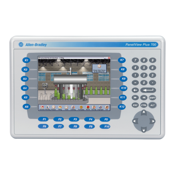
What are the F and K buttons on the touchscreen represent

1 comments:
Mr. Anderson
February 26, 2025

The F and K buttons on the Allen-Bradley PanelView Plus 2711P touchscreen are programmable function keys. They are used to initiate functions on the terminal display and may have custom legends. The number of function keys varies by model:
- 700: F1-F10, K1-K12
- 1000: F1-F16, K1-K16
- 1250: F1-F20, K1-K20
- 1500: F1-F20, K1-K20

This answer is automatically generated

Diprajsinh
April 21, 2025

In allen bradley panel view plus 1250 where is fuse located

Summary of Contents for Allen-Bradley PanelView Plus 2711P

  • Page 1 2711P PanelView Plus Operator Terminals 700, 1000, 1250, 1500 User Manual AB PLCs...
  • Page 2 (to include intellectual property liability) for actual use based upon the examples shown in this publication. Allen-Bradley publication SGI-1.1, Safety Guidelines for the Application, Installation and Maintenance of Solid-State Control (available from your local Rockwell Automation office), describes...
  • Page 3: Table Of Contents

    Table of Contents Preface Objectives....... . . Preface-i Packing List ....... Preface-i Manual Contents .
  • Page 4 Table of Contents Terminal Settings ....... 4-5 Networks and Communications ..... 4-6 Diagnostic Setup .
  • Page 5 Table of Contents Chapter 8 Troubleshooting and Maintenance Chapter Objectives ......8-1 General Troubleshooting .
  • Page 6 Table of Contents Publication 2711P-UM001A-EN-P...
  • Page 7: Objectives

    Preface Objectives This preface provides information on the contents of this manual including: • contents of manual • intended audience • European Union Directive Compliance • Rockwell Automation Support Packing List The following items are shipped with an assembled PanelView Plus terminal: •...
  • Page 8: Manual Contents

    Preface Manual Contents Chapter Title Description Overview Provides overview of the PanelView Plus terminals including features and product components. Installation Gives Instructions on how to install the PanelView Plus terminal in a panel or enclosure. Applying Power Describes how to apply power and reset the PanelView Plus terminal.
  • Page 9: Related Publications

    Programmable Controllers, Part 2 - Equipment Requirements and Tests. For specific information required by EN 61131-2, see the appropriate sections in this publication, as well as the Allen-Bradley publication Industrial Automation Wiring and Grounding Guidelines For Noise Immunity, publication 1770-4.1.
  • Page 10: Rockwell Automation Support

    Preface Rockwell Automation Before you contact Rockwell Automation for technical assistance, we suggest you please review the troubleshooting information contained Support in this publication first. If the problem persists, call your local Rockwell Automation representative or contact Rockwell Automation in one of the following ways: Phone United...
  • Page 11: Chapter 1 Chapter Objectives

    Chapter Overview Chapter Objectives This chapter gives an overview of the PanelView Plus terminals including: • hardware features • software support • modular components • base configured unit • communication modules • remote AC power supply • display modules • catalog number configuration and product components Hardware Features The PanelView Plus terminals are operating and display devices that run RSView Machine Edition (V3.0 or later).
  • Page 12: Software Support

    Overview Software Support RSView Machine Edition runtime (3.0 or later) is included with the PanelView Plus terminal and does not require activation. Modular Components The PanelView Plus terminals use modular components allowing for flexible configuration, installation, and upgrades. Items can be ordered as separate components or factory assembled per your configuration.
  • Page 13: Base Configured Unit

    Overview Base Configured Unit The base configured unit of the PanelView Plus terminal consists of: • Display Module (700, 1000, 1250, 1500) with Keypad, Touch or Keypad & Touch Input • Logic Module The Logic Module contains: • 24V dc input (18…32V dc) •...
  • Page 14: Communication Modules

    Overview Communication Modules You can attach a separate Communication Module to the base configured unit of the PanelView Plus terminal to increase your communications capability. • DH+/DH485/Remote I/O The Communication Modules install easily on top of the Logic Module on the back of the unit. Communication Module Remote AC Power Supply The Logic Module provides a DC power input.
  • Page 15: Display Modules

    Field replaceable bezels are also available. Touch Screen The following illustration shows a 1000 touch screen display. All of the touch screen displays are analog resistive and similar except for size. Allen-Bradley Label IrDA Port Touch Screen AB PLCs Publication 2711P-UM001A-EN-P...
  • Page 16 (F1-F16, K1-K16) custom legends. 1250 (F1-F20, K1-K20) 1500 (F1-F20, K1-K20) Label Allen-Bradley or customer applied label. IrDA Port For data or application transfers. Numeric Keypad 0-9, ., -, Backspace, Enter, Tab, Shift, Esc, Ctrl, Alt keys Navigation Keys Use the arrow keys to move cursor in lists,...
  • Page 17: Catalog Number Configuration

    Overview Catalog Number The following table shows the catalog number configuration for PanelView Plus terminals. Configuration Input Size Type Comms Power Memory Label Flash/RAM 2711P- K = Keypad 7 = 6.5 inch C = Color 4 = Standard Communication (Ethernet & RS-232) B = AC DIN 1= 32 MB/64 MB Blank =AB Label...
  • Page 18 Overview Remote AC Power Supply Cat. No. Description 2711P-RSACDIN AC to DC DIN Rail Power Supply, 85…265V ac, 47…63 Hz Logic Module Cat. No. Description 2711P-RP Logic Module without memory Internal Compact Flash Cards Cat. No. Description 2711P-RW1 32 MB Compact Flash with RSView Machine Edition 2711P-RW2 128 MB Compact Flash with RSView Machine Edition 2711P-RW3...
  • Page 19 Overview Legend Kits Cat. No. Description 2711P-RFK7 Replacement Legend Strips for 700 Keypad Terminal 2711P-RFK10 Replacement Legend Strips for 1000 Keypad Terminal 2711P-RFK12 Replacement Legend Strips for 1250 Keypad Terminal 2711P-RFK15 Replacement Legend Strips for 1500 Keypad Terminal Protective Antiglare Overlays Cat.
  • Page 20 1-10 Overview Adapter Plates Cat. No. Description 2711P-RAK7 Adapts a PanelView Plus 700 Keypad Terminal to a PanelView Standard 900 Keypad Cutout 2711P-RAT7 Adapts a PanelView Plus 700 Touch Terminal to a PanelView Standard 900 Touch Cutout 2711P-RAK10 Adapts a PanelView Plus 1000 Keypad Terminal to a PanelView 1000/1000E Keypad Cutout 2711P-RAT10 Adapts a PanelView Plus 1000 Touch Terminal to a PanelView...
  • Page 21: Chapter 2 Chapter Objectives

    Chapter Installation Chapter Objectives This chapter provides instructions on how to install the PanelView Plus terminals. It provides information on: • hazardous locations • environment • enclosures • clearances • required tools • mounting dimensions • cutout dimensions • panel installation Hazardous Locations This PanelView Plus terminals are suitable for use in: •...
  • Page 22: Environmental Considerations

    Installation Environmental The PanelView Plus terminals are suitable for use in an industrial environment when installed in accordance with these instructions. Considerations Specifically, this equipment is intended for use in clean, dry environments (Pollution Degree 2 and with circuits not exceeding Over Voltage Category II (IEC 60664-1).
  • Page 23: Mounting Dimensions

    Installation Mounting Dimensions This section provides mounting dimensions for the PanelView Plus terminals. The depth dimensions are shown for: • base configured unit (Display Module and Logic Module) • base configured unit with Communication Module All dimensions are in mm (inches). PanelView Plus 700 700 Keypad or Keypad &...
  • Page 24 Installation PanelView Plus 1000 1000 Keypad or Keypad & Touch Terminal a 55 (2.18) Display to Logic Module b 83 (3.27) Display to Communication Module (9.77) (15.72) 1000 Touch Screen Terminal a 55 (2.18) Display to Logic Module b 83 (3.27) Display to Communication Module (9.77) (12.97) Publication 2711P-UM001A-EN-P...
  • Page 25 Installation PanelView Plus 1250 1250 Keypad or Keypad & Touch Terminal a 55 (2.18) Display to Logic Module (11.12) b 83 (3.27) Display to Communication Module (16.36) 1250 Touch Screen Terminal a 55 (2.18) Display to Logic Module b 83 (3.27) Display to Communication Module (11.12) (14.30) AB PLCs...
  • Page 26 Installation PanelView Plus 1500 1500 Keypad or Keypad & Touch Terminal (12.97) a 65 (2.55) Display to Logic Module b 93 (3.65) Display to Communication Module (18.46) 1500 Touch Screen Terminal a 65 (2.55) Display to Logic Module b 93 (3.65) Display to Communication Module (12.97) (16.37) Publication 2711P-UM001A-EN-P...
  • Page 27: Cutout Dimensions

    Installation Cutout Dimensions This section provides panel cutout dimensions for each terminal. Use the full size template shipped with your terminal to mark the cutout dimensions. All dimensions are in mm (inches). PanelView Plus Terminal Height Width PanelView Plus 700 Keypad or Keypad & Touch 167 (6.57) 264 (10.39) PanelView Plus 700 Touch...
  • Page 28: Panel Installation

    Installation Panel Installation All of the PanelView Plus terminals are installed in the same manner using clips for mounting. The number of clips used (4, 6 or 8) varies by terminal type. The mounting clips are shipped with each terminal. •...
  • Page 29 ATTENTION of .90 - 1.1 N•m (8 - 10 in-lb) to provide a proper seal and to prevent potential damage to the terminal. Allen-Bradley assumes no responsibility for water or chemical damage to the terminal or other equipment within the enclosure because of improper installation.
  • Page 30 2-10 Installation Publication 2711P-UM001A-EN-P...
  • Page 31: Chapter 3 Chapter Objectives

    Chapter Applying Power Chapter Objectives This chapter provides information: • wiring and safety guidelines • connecting DC power • connecting AC power • resetting the terminal • powerup sequence Wiring and Safety Use publication NFPA 70E, Electrical Safety Requirements for Employee Workplaces when wiring the PanelView Plus terminals.
  • Page 32: Applying Dc Power

    Applying Power Applying DC Power The PanelView Plus terminals have an integrated power supply that operates on 24V dc. The electrical input ratings are: • 24V dc nominal (18…32V dc) • 70 Watts maximum (2.9A @24V dc) The power supply is internally protected against reverse polarity. The input power, terminal block on the power supply is removable and supports the following wire sizes: Wire Size...
  • Page 33: Applying Ac Power

    Applying Power Applying AC Power Connecting to AC power requires the AC Power Supply (2711-RSACDIN) that mounts to a DIN Rail. This power supply converts DC power to AC power and has the following electrical input ratings: • 85…264 V ac (47…63 Hz) •...
  • Page 34: Startup Sequence

    Applying Power • Insert a thin probe into the hole marked DEFAULT and press the switch, then; • Insert the probe into the hole marked RESET and press the switch. The system will restart immediately into the Safe Mode. Use a nonconducting object to press the RESET and ATTENTION DEFAULT switch.
  • Page 35: Chapter 4 Chapter Objectives

    Chapter Using Configuration Mode Chapter Objectives This chapter shows how to use the configuration screens of your PanelView Plus terminal to: • perform data entry and navigation • load an ME application • run an ME application • modify application settings •...
  • Page 36 Using Configuration Mode Main Screen Button Description Load Application (F1) Opens another screen where you can select an application to load. Once loaded, the application name will appear under Current Application. Run Application (F2) Runs the .MER application displayed under Current Application. An application must be loaded before you can run it.
  • Page 37 Using Configuration Mode Input Panel Many screens have buttons that access fields where you must enter/edit data. When you press the button or function key, the Input Panel opens ready for you to input data. If the field is restricted to a numeric value, only the 0-9 keys will be enabled.
  • Page 38: Loading An Me Application

    Using Configuration Mode Loading an ME Application To load an RSView ME .MER application, select the Load Application button on the main screen: List of .mer applications stored in the compact Moves flash of the terminal. highlight up Moves highlight down 1.
  • Page 39: Running An Application

    Using Configuration Mode Running an Application To run the currently loaded application, select the Run Application button on the main Configuration Mode screen. An application must be loaded, before you can run it. Log files generated by the application may be deleted if this option was selected on the main screen or enabled as a Startup Option under Terminal Settings.
  • Page 40: Networks And Communications

    Using Configuration Mode Terminal Setting Description System Event Log Displays a list of system events currently logged by the terminal. System Information Displays power, temperature, battery and memory details for the terminal. Also shows the firmware number for RSView ME and technical support information. Time/Date/Regional Settings Sets the date, time, language and numeric format used by the terminal and applications.
  • Page 41 Using Configuration Mode RSLinx Communications Terminal Settings Networks and Communications The RSLinx Communications screen shows a treeview of installed communication cards and network configurations. You can: RSLinx Communications • edit/view the driver settings for the communication protocol used by your .MER application. •...
  • Page 42 Using Configuration Mode To edit communication settings: 1. From the RSLinx Configuration Screen, select the communication card installed on your terminal. 2. Select the Driver Settings button. A properties screen opens showing the current communication settings for the driver. 3. To modify a setting, select the setting and then the Edit button. The Input Panel opens showing the current setting.
  • Page 43 Using Configuration Mode DHPlus Properties The DHPlus Properties screen lets you view or modify settings for a PanelView Plus connected to a DHPlus network. Field Description Valid Values Jumper ID Identifies the communication card if multiple 0 - 3 cards are installed on terminal. Station Number The unique address of the PanelView Plus on 0 - 77 (octal)
  • Page 44 4-10 Using Configuration Mode Serial Properties The Serial Properties screen configures settings for serial communications (using the RS-232 serial port) on the PanelView Plus terminal. Field Description Valid Values Device The serial device your PanelView Plus PLC_CH0 terminal is connected to. SLC_CH0 KFC15 AC_CH0...
  • Page 45 Using Configuration Mode 4-11 Network Connections Terminal Settings Networks and Communications The Network Connections screen lets you configure the following for the PanelView Plus terminal: Network Connections • Device Name • Network Adapters • Network Identification Device Name Terminal Settings Networks and Communications The Device Name screen identifies the PanelView Plus terminal to other computers on the network.
  • Page 46 4-12 Using Configuration Mode Network Adapters Terminal Settings Networks and Communications The Network Adapters screen configures driver settings for all network adapters installed on the terminal. The only network adapter Network Connections on the PanelView Plus terminal is the (IntelR) Fast Ethernet Controller. Network Adapters Press the Name Servers button and/or IP Address button to access driver settings.
  • Page 47 Using Configuration Mode 4-13 IP Address The IP Address screen identifies the IP address of the selected network adapter. If the network the PanelView Plus is connected to does not automatically assign an IP address, you can assign the address in this screen. Field Description Valid Values...
  • Page 48 4-14 Using Configuration Mode Network Identification Terminal Settings Networks and Communications The Network Identification screen configures settings that enable the PanelView Plus terminal to gain access to network resources. You can Network Connections enter a user name, password and domain (provided by your network administrator).
  • Page 49: Diagnostic Setup

    Using Configuration Mode 4-15 Diagnostic Setup The Diagnostic Setup screen configures diagnostics for the current computer. The screen shows a treeview of possible diagnostic nodes. Terminal Settings To access the Remote Log Setup or Message Diagnostic Setup Routing, select the node and then the Edit button.
  • Page 50: File Management

    4-16 Using Configuration Mode File Management The File Management screen lets you access screens to: • Delete Files • Copy Files Delete Files Terminal Settings From the Delete Files screen you can select options to: File Management • Delete Applications - deletes an .MER application file from a Delete Files storage location.
  • Page 51 Using Configuration Mode 4-17 Delete Log Files Select this option to delete any data log files, alarm history files and alarm status files in the System Default location on the PanelView Plus terminal. You will be asked to confirm the operation. Do you want to delete all of the RSView ME Station Log Files? Select Yes or No.
  • Page 52: Display

    4-18 Using Configuration Mode 2. Select the Destination button on the same screen to open the following screen. 3. Select the Destination button to select the storage location where you want to copy the application or font file to. • Internal Storage - the Internal Compact Flash in the PanelView Plus terminal.
  • Page 53 Using Configuration Mode 4-19 Display Intensity Terminal Settings Display The Display Intensity screen lets you view or modify the current intensity of the backlight. The default intensity is 100%. When you Display Intensity change the intensity, the terminal temporarily changes to that intensity.
  • Page 54: Input Devices

    4-20 Using Configuration Mode Input Devices The Input Devices screen lets you access screens to view and modify settings for: • Keyboard • Keypad • Mouse • Touch Screen Keyboard and Keypad Setup The Keyboard and Keypad screen opens these screens: •...
  • Page 55 Using Configuration Mode 4-21 Key Settings for Attached Keyboard The Keyboard Settings screen enables or disables the Ctrl-Alt-Esc option. This key sequence is equivalent to the Ctrl-Alt-Del sequence on a computer. The default is currently enabled. Key Settings for PanelView Plus Keypad The Keypad Settings screen enables/disables Single Key Mode option which is used to restrict multiple or simultaneous key presses.
  • Page 56 4-22 Using Configuration Mode Touch Screen Terminal Settings Input Devices The Touch Screen lets you access the following screens: • Calibration Touch Screen • Cursor • Double-Tap Sensitivity Touch Screen Calibration This screen calibrates the touch screen of the PanelView Plus terminal. Touch the center of the target (+) each of the 4 times it appears.
  • Page 57 Using Configuration Mode 4-23 Double-Tap Sensitivity This screen lets you set and test the sensitivity for both speed and physical distance between touch screen presses. • The Set button sets the sensitivity of touch screen presses. • The Test button tests the sensitivity of touch screen presses. If you double-tap the test button with the time set using the Set button, the Test button will reverse it’s foreground and background colors.
  • Page 58: Print Setup

    4-24 Using Configuration Mode Print Setup The Print Setup screen lets you access screens to configure print options for: • Displays • Alarms • Diagnostic messages. Display, Alarm , and Diagnostic Print Setup Terminal Settings Networks and Communications The general setup for printing displays, alarm messages and diagnostics messages from an RSView .MER application is the same.
  • Page 59 Using Configuration Mode 4-25 Advanced Settings for Diagnostic Messages and Alarm Messages The following screen configures when to print diagnostic or alarm messages that are sent to the Network or USB port. To configure how messages are queued for printing, select the Print Messages After button and set one of the following options: •...
  • Page 60: Startup Options

    4-26 Using Configuration Mode Startup Options The Startup Options screen accesses the following screens to modify: • RSView ME Station Startup • Startup Tests Terminal Settings RSView ME Station Startup Startup Options The RSView Machine Station Startup screen specifies what action the PanelView Plus terminal takes on startup: RSView ME Station Startup •...
  • Page 61 Using Configuration Mode 4-27 Configuration Mode The Configuration Mode Options screen specifies whether the PanelView Plus will boot up in Configure Mode: • with the current application loaded. • with the communication configuration of the current application or the terminal’s RSLinx communication configuration. If you select Yes to replace the terminal’s communication configuration with that of the application, any changes made to the device addresses or driver properties in the RSLinx...
  • Page 62 4-28 Using Configuration Mode Startup Tests Terminal Settings Startup Options The PanelView Plus can run extended tests on startup. The Startup Tests screen provides access to these screens: Startup Tests • Startup Tests Settings • Repeat Count Select Tests The Select Tests screen shows a list of each test that can be performed on the PanelView Plus terminal at startup and its current On/Off status.
  • Page 63 Using Configuration Mode 4-29 Startup Tests Settings From the Startup Tests Settings screen, you can: • enable extended diagnostics to run on the terminal at startup • disable extended diagnostics at startup • specify how many times to repeat the selected tests that are run on the terminal during startup.
  • Page 64: System Event Log

    4-30 Using Configuration Mode System Event Log The System Event Log screen displays a list of system events currently logged by the PanelView Plus terminal. Terminal Settings System Event Log • To display System Event Log Details for a specific event, select an event and then select the More Details button.
  • Page 65: System Information

    Using Configuration Mode 4-31 System Information The System Information screen lets you access: • RSView ME Station information • Terminal Information Terminal Information Terminal Settings System Information The Terminal Information screen displays the following details for the PanelView Plus terminal: Terminal Information •...
  • Page 66 4-32 Using Configuration Mode Memory Allocation The Memory Allocation screen displays: • amount of allocated storage or program memory • amount of storage or program memory currently in use You can modify the allocation of storage or program memory. Press the Up or Down button to increase/decrease the memory allocation.
  • Page 67 Using Configuration Mode 4-33 RSView ME Station Information Terminal Settings System Information The About RSView ME Station screen provides access to: • RSView ME Station firmware number About RSView ME Station • Rockwell Technical Support information AB PLCs Publication 2711P-UM001A-EN-P...
  • Page 68: Time/Date/Regional Settings

    4-34 Using Configuration Mode Time/Date/Regional The Time/Date/Regional Settings screen lets you access the following screens to set: Settings • date • regional settings • time • time zone Date Terminal Settings Time/Date/Regional Settings The Date screen shows and configures the current date in separate Year, Month and Day fields.
  • Page 69 Using Configuration Mode 4-35 Time Terminal Settings Time/Date/Regional Settings The Time screen shows and configures the current time in 24-hour format in separate Hour, Minute and Second fields. Time Field Description Valid Values Hour The current hour in 24-hour format. 0 - 23 Minute The current minute in 24-hour format.
  • Page 70 4-36 Using Configuration Mode Time Zone Terminal Settings Time/Date/Regional Settings The Time Zone screen shows the current time zone that is installed on the PanelView Plus terminal. Time zones are installed as a part of the Time Zone operating system. Changing the time zone adjusts the current time and date to match the new time zone.
  • Page 71 Using Configuration Mode 4-37 Regional Settings Terminal Settings The Regional Settings screen allows you to access these screens: Time/Date/Regional Settings • Language Regional Settings • Numeric Format • Long Date Format • Short Date Format • Time Format The current language is shown at the bottom of the Regional Settings screen.
  • Page 72 4-38 Using Configuration Mode Time Format Terminal Settings The Time Format screen configures the time format for the current Time/Date/Regional Settings language. A sample of the current time is shown using the currently selected format. Regional Settings Time Format Field Description Example h:mm:ss tt (default)
  • Page 73 Using Configuration Mode 4-39 Short Date Format Terminal Settings The Short Date Format screen configures the short date format used Time/Date/Regional Settings by the current language. A sample of the current date is shown using Regional Settings the currently selected short date format. Short Date Format Field Short Date Formats...
  • Page 74 4-40 Using Configuration Mode Long Date Format Terminal Settings The Long Date Format screen configures the long date format used by Time/Date/Regional Settings the current language. A sample of the current date is shown using the Regional Settings currently selected long date format. Long Date Format Field Short Date Formats...
  • Page 75: Chapter 5 Chapter Objectives

    Chapter Installing and Replacing Components Chapter Objectives This chapter shows how to install, replace or upgrade various components of the PanelView Plus terminal, including: • Logic Module • RAM and Internal Compact Flash • Communication Module • Display Module • Battery •...
  • Page 76: Installing Ram And Internal Compact Flash

    Installing and Replacing Components Installing RAM and Internal The Logic Module (2711P-RP) of the PanelView Plus terminal does not contain RAM (2711P-RRxxx) or Internal Compact Flash (2711P-RWx) Compact Flash when ordered as a separate component. You must install the RAM and Internal Compact Flash before attaching the Logic Module to the Display Module.
  • Page 77: Installing And Replacing The Logic Module

    Installing and Replacing Components Installing and Replacing This section shows how to install and replace the Logic Module (2711P-RP) of the PanelView Plus terminal. If the Display Module and the Logic Module Logic Module are ordered as separate components, attach the Logic Module to the Display Module before panel installation.
  • Page 78 Installing and Replacing Components To replace the Logic Module: Before replacing the Logic Module, you must remove the Communication Module (if attached). You will also need to remove the Internal RAM and Compact Flash from the Logic Module to reuse in the new Logic Module.
  • Page 79: Installing/Replacing A Communication Module

    Installing and Replacing Components Installing/Replacing a This section shows how to install and replace a Communication Module on the PanelView Plus terminal. The Communication Module Communication Module installs over the Logic Module. The Communication Modules are available as separate catalog numbers for specific communication protocols.
  • Page 80 Installing and Replacing Components 4. Position the Communication Module over the Logic Module so that the connectors on bottom of module align with connectors on Logic Module. 5. To prevent Electrostatic Discharge (ESD) between the modules, allow the Communication Module to touch the Logic Module before making connection.
  • Page 81: Replacing The Display Module

    Installing and Replacing Components Replacing the Display This sections shows how to replace the Display Module (2711P-RDxxxx). It is necessary to remove the Communication Module Module from the Logic Module to perform this operation. Communication Module Logic Module Display Module 1.
  • Page 82 Installing and Replacing Components 7. Position the new Logic Module over the new Display Module so that the connectors align. 8. Push down on the Logic Module until firmly seated. 9. Tighten the 6 captive screws that secure the Logic Module to the Display Module to a torque of .68 N•m 6-8 in-lb).
  • Page 83: Replacing The Battery

    Installing and Replacing Components Replacing the Battery The lithium battery (2711P-RY2032) is used by the real-time clock and static RAM; it is not used for application backup or retention. The clock module has a life expectancy of 2 years without power. When you connect or disconnect the battery an WARNING electrical arc can occur.
  • Page 84 5-10 Installing and Replacing Components 5. Carefully lift the Logic Module away from the terminal and flip over to expose the circuit board. Wear a properly ground ESD wristband IMPORTANT before touching any of the electronic components in the Logic Module. 6.
  • Page 85: Replacing Bezel

    Installing and Replacing Components 5-11 Replacing Bezel Removing Display Module Bezel It is not necessary to remove the Logic Module or Communication Module before removing the bezel, except for the PanelView Plus 700. 1. Disconnect power from the terminal. 2. Set the terminal, display side down, on a flat stable surface. Wear a properly ground ESD wristband IMPORTANT before touching any of the electronic...
  • Page 86 5-12 Installing and Replacing Components 6. Lift the back of the Display Module away from the bezel. Work on a clean, flat, stable surface to protect the display from debris, scratches and damage. Display Module Bezel 7. Detach all connectors (maximum of 3). The number of connectors varies by model.
  • Page 87: Replacing Backlight

    Installing and Replacing Components 5-13 Replacing Backlight This section shows how to replace the backlight for the 700, 1000, and 1250 models. The 1500 does not have a replaceable backlight. 1. Disconnect power from the terminal. 2. Remove Display Module bezel as described on page 5-11. 3.
  • Page 88 5-14 Installing and Replacing Components 5. Detach the Backlight Connector from the circuit board. The 1250 has two Backlight Connectors. Backlight Connector For PanelView Plus 700/1000 Work on a clean, flat, stable surface to protect the display from debris, scratches and damage. 6.
  • Page 89 Installing and Replacing Components 5-15 For PanelView Plus 1250 (has 2 Backlights) Work on a clean, flat, stable surface to protect the display from debris, scratches and damage. 8. Remove the 2 screws that secure each of the two backlights and then remove the backlights.
  • Page 90: Installing The Remote Ac Power Supply

    If you ordered a PanelView Plus terminal with a label, you can remove it and attach your own label. Label 1. Remove the Allen-Bradley label using your fingers or a tweezers. 2. Clean area with damp cloth and isopropyl alcohol. 3. Remove adhesive backing of OEM label and affix over area where Allen-Bradley label was located.
  • Page 91: Installing Keypad Legend Inserts

    Installing and Replacing Components 5-17 Installing Keypad Legend This section shows how to replace the legend inserts in the PanelView Plus keypad terminals. The legend strips are available as separate Inserts catalog numbers (2711P-RFKxx) for each keypad version of the terminals.
  • Page 92: Using An External Compact Flash Card

    5-18 Installing and Replacing Components To replace the K1-K22 function key legends: 1. Remove power from the terminal. 2. Remove the Display Module bezel as described on page 5-11. 3. Pull the legend inserts out from the slots on the lower part of the bezel.
  • Page 93 Installing and Replacing Components 5-19 Inserting a Compact Flash Card 1. Insert the card in the Compact Flash Card slot of the terminal until firmly seated. Removing a Compact Flash Card 1. Press the Eject button above the card slot. When the button pops out, press it again to release the card.
  • Page 94 5-20 Installing and Replacing Components Publication 2711P-UM001A-EN-P...
  • Page 95: Chapter 6 Chapter Objectives

    Chapter Terminal Connections Chapter Objectives This chapter provides network and device connections for the PanelView Plus terminals, including: • wiring and safety guidelines • Logic Controller Cable Charts • USB Ports • Serial connections on base unit • Ethernet (onboard communications) •...
  • Page 96: Logic Controller Cable Charts

    Terminal Connections Logic Controller Cable Refer to the following charts for a summary of PanelView Plus terminal connections to controllers and network interface modules. Charts Runtime Communication Cables - To Controllers Cables: PanelView Plus to Processor SLC-500, 5/01, 5/02 SLC-5/03, 5/04, 5/05 SLC 5/03 SLC 5/04 SLC 5/05...
  • Page 97 Terminal Connections Cables: PanelView Plus to Processor MicroLogix 1000, 1200, PLC-5, PLC-5C, PLC-5E ControlLogix 1500LSP Protocol PanelView Plus Comm Port CH0 (25-pin RS-232) CH0 (9-pin RS-232) CH0 (8-pin Mini DIN) (DF1) (DF1) (DF1 or DH-485) RS-232 (DF1) Comm Port (9-pin) 2711-NC21 (16ft/5m) 2711-NC13 (16ft/5m) (any)
  • Page 98: Usb Ports

    Terminal Connections Cables: PanelView Plus to Communication Adapters 1761-NET-AIC 1747-AIC Port 2 Port 3 1761-NETDNI Protocol PanelView Plus Comm Port Port 1 (9-pin) 8-pin Mini DIN() (DH485) or 1771-NET-ENI DF1 (any) RS-232 Comm Port (9-pin) 2711-NC13 (16ft/5m) 2711-NC21 (16ft/5m) 2711-NC21 (16ft/5m) PanelView Plus 700 -1500 2711-NC14 (32ft/10m) 2711-NC12 (32ft/10m)
  • Page 99: Serial Connections

    Terminal Connections Serial Connections The base configured unit of the PanelView Plus terminal has a multi-purpose serial RS-232 port that supports: • DH-485 communications through a serial connection • DF1 full duplex communications with controllers using direct connections or modem connections •...
  • Page 100 Terminal Connections Modem Connection Wire or radio modem communications is possible between the PanelView Plus and controller. Each modem must support full duplex communications. Refer to your modem user manual for details on settings and configuration. PanelView Plus Optical Isolator Controller DF1 Port Modem...
  • Page 101 Terminal Connections Computer or Printer Connections The RS-232 serial port on the base configured unit of the PanelView Plus terminal supports: • application uploads/downloads using a direct connection • or printing Base Configured Unit of PanelView Plus Computer Available Cables Cat.
  • Page 102: Ethernet Connections

    Terminal Connections Ethernet Connections The base configured unit of the PanelView Plus terminal has an Ethernet port that supports: • EtherNet/IP communications • third party Ethernet communications • network connections • application uploads/downloads • printing Ethernet Connector The base unit configured unit of the PanelView Plus terminal has an RJ45, 10/100Base-T connector for EtherNet/IP or Ethernet TCP/IP network communications.
  • Page 103 Terminal Connections Cables Category 5 shielded and unshielded twisted-pair cables with RJ45 connectors are supported. If 100 Mbit/second data rates are used, we recommend that you use a shielded cable. The shielded cable will help insure that industrial noise immunity levels are maintained. The maximum cable length between the terminal’s Ethernet port and a 10/100Base-T port on an Ethernet hub (without repeaters or fiber) is 100 meters (328 feet).
  • Page 104: Dh-485/Dh+/Remote I/O Module

    6-10 Terminal Connections DH-485/DH+/Remote I/O The PanelView Plus terminal with a DH-485/DH+/Remote I/O Communication Module supports communications with the following Module networks: • DH+ networks • DH-485 networks • Remote I/O networks You can communicate with only one network at one time. Module Connections Allen Bradley...
  • Page 105 6-11 DH-485 Network Port Wiring Use these instructions for wiring Belden cable. If you are using standard Allen-Bradley cables, see the Cable section on page 6-2. Attaching RS-485 Connector to the Communication Cable A daisy-chained network is recommended. We do IMPORTANT not recommend the following.
  • Page 106 6-12 Terminal Connections DHPlus Network Connections Use the Belden 9463 twin axial cable (1770-CD) to connect a PanelView Plus terminal to the DH+ link. You can connect a DH+ link in 2 ways: • trunk line/drop line - from the drop line to the connector screw terminals on the DH+ connectors of the processor •...
  • Page 107 Terminal Connections 6-13 Remote I/O Connections To connect a PanelView Plus terminal to a Remote I/O scanner, use cable Catalog No. 1770-CD (equivalent to Belden 9463). The maximum cable length (link distance) is determined by the baud rate. • 2,800 meters (10,000 feet) for 57.6K baud •...
  • Page 108 6-14 Terminal Connections Publication 2711P-UM001A-EN-P...
  • Page 109: Chapter 7 Chapter Objectives

    Chapter Transferring files Chapter Objectives This chapter covers information on: • transferring applications using a Compact Flash Card For details on transferring .MER applications from a IMPORTANT computer to the PanelView Plus terminal, refer to RSView Studio help or documentation. Using a Compact Flash Card The PanelView Plus terminal allows you to copy or load files using a compact flash card from RSView ME.
  • Page 110 Transferring files Publication 2711P-UM001A-EN-P...
  • Page 111: Troubleshooting And Maintenance

    Chapter Troubleshooting and Maintenance Chapter Objectives This chapter provides information on how to isolate and correct common operating problems with system components. • general troubleshooting • troubleshooting individual components (display, touch screen, keypad, attached keyboard or mouse) • Ethernet • startup •...
  • Page 112 Troubleshooting and Maintenance If the terminal powers up and stops during startup, the state of the Logic Module LEDs indicate the following: Blinking red LED indicates a recoverable error. Red LED Green LED Description Blinking Last firmware download failed. Repeat firmware download.
  • Page 113: Troubleshooting Components

    Troubleshooting and Maintenance Select one or more of the tests you want to run. Enable extended diagnostics and set the iteration or repeat count. Restart the PanelView Plus terminal. The Serial Port test requires a loopback connector with the following connections. DB9 Connector (female) Extended Diagnostics are performed at every startup until disabled.
  • Page 114 Troubleshooting and Maintenance • Check the startup messages. Is the Display operating at all and do the startup messages appear? Record any error message and use the System Error Message table on page 8-9 for troubleshooting. • Replace the Display Module if all other attempts do not resolve problem.
  • Page 115 Troubleshooting and Maintenance Keypad Problems This section provides tips on how to isolate problems with the Keypad: • Check Multi-Key/Hold-Off settings. From Configuration Mode, open Terminal Settings>Keypad>Keypad Settings. Is the Hold-Off Delay longer than expected, or are multiple key presses being held by Multi-Key Lockout? Check all configurable settings.
  • Page 116 Troubleshooting and Maintenance • Check for enabled Alt-Ctrl keys. From Configuration Mode, open Terminal Settings>Input Devices>Keyboard>Keyboard Settings. Are the keys enabled as expected? Check all configurable settings in Keyboard Properties. • If keypad is present, check input using the keypad. If the keypad works, but the keyboard does not, then the keyboard driver or keyboard is probably not working.
  • Page 117: Ethernet Problems

    Troubleshooting and Maintenance • Check LED indicators at the Ethernet connector. The green Ethernet Problems LED indicates a communications link and should be ON. The amber LED indicates data activity and should be flashing. Verify that there is a connection to the hub? •...
  • Page 118: Advanced Troubleshooting

    Troubleshooting and Maintenance Advanced Troubleshooting 1. Take advantage of alternate connectivity - mouse versus touch screen, keyboard versus keypad, serial communications, and alternate Ethernet connections. 2. Know useful keyboard shortcuts so that you can navigate around the system without a mouse or touch screen. 3.
  • Page 119: System Error Messages

    Troubleshooting and Maintenance System Error Messages The following table provides a list of system error messages that may display on startup. Error Number Displayed Message Description RAM Test POST RAM Test failure Internal CF Internal Compact Flash Card access failure EXE Valid System firmware is incompatible with the boot loader...
  • Page 120: System Identification Errors

    8-10 Troubleshooting and Maintenance System Identification Errors The error messages in this section appear on bootup if incorrect or invalid components are used with the PanelView Plus terminal. • The following dialog appears if a VersaView CE Logic Module is attached to a PanelView Display Module or a PanelView Plus Logic Module is attached to a VersaView CE Display Module.
  • Page 121: Restarting In Configuration Mode

    Troubleshooting and Maintenance 8-11 • The following dialog appears if the Internal Compact Flash in the PanelView Plus Logic Module is corrupt or invalid. This is a fatal error After pressing OK, you will be asked to power of the terminal and insert a valid 6189-RWx Internal Compact Flash card.
  • Page 122: Startup Problems

    8-12 Troubleshooting and Maintenance Startup Problems If the PanelView Plus terminal does not enter Configuration Mode on startup, then reload the firmware. See page8-13 for details. If the application does not start, there may be a problem with the .mer RSView Machine Edition file.
  • Page 123: Firmware Upgrade

    Troubleshooting and Maintenance 8-13 Firmware Upgrade Application firmware can be downloaded using an Ethernet or serial connection from a desktop computer running the Firmware Upgrade Wizard. This wizard is available from the customer support website. 1. Establish a serial or Ethernet connection to a desktop computer. The serial connection uses the 2706-NC13 cable or equivalent.
  • Page 124: Cleaning The Display Window

    8-14 Troubleshooting and Maintenance Cleaning the Display Window Use of abrasive cleaners or solvents may damage the ATTENTION display. Do not scrub or use brushes. To clean the display window: 1. Disconnect power from the terminal at the power source. 2.
  • Page 125: Appendix A - Specifications

    Appendix Specifications Electrical DC Power Input Voltage DC 24V dc nominal (18…32V dc) Power Consumption DC 70 Watts maximum (2.9A @24V dc) AC Power (2711P-RSAC) Input Voltage AC 85…264V ac, 47…63 Hz Power Consumption AC 120VA maximum Environmental Operating Temperature 0…55 °C (32…131 °F) Non-operating Temperature -25…70 °C (-13 to 158 °F)
  • Page 126 Specifications Mechanical Weight (for base unit without modules) 700 Keypad or Keypad & Touch 1.9 kg (4.2 lbs) 700 Touch 1.7 kg (3.8 lbs) 1000 Keypad or Keypad & Touch 2.9 kg (6.3 lbs) 1000 Touch 2.6 kg (5.7 lbs) 1250 Keypad or Keypad &...
  • Page 127 Index 1-4, 1-8 4-34 AC power supply date 4-39 electrical ratings date format 5-16 installation DC power accessories connections 1-10 adapter plates electrical ratings antiglare overlays SELV power supply deleting files application 4-16 applications loading .mer 4-16 font files running .mer 4-16 log files DH485...
  • Page 128 Index input devices memory 4-20 4-32 keyboard allocations 4-20 keypad installing and replacing 4-23 mouse modular components 4-22 touch screen 1-9, 2-9 mounting clips input panel mounting dimensions installation 1000H 1000H mounting dimensions 1250H 1250H mounting dimensions 1500H 1500H mounting dimensions 700H 700H mounting dimensions 4-23, 6-4...
  • Page 129 Index DH485 Remote I/O 4-33 null modem cable RSView ME info 6-5, 6-8 4-19 ports screen saver 6-5, 6-7 4-10 printing serial 4-39 transferring applications short date format 4-26 using a modem startup options 4-28 serial connections startup tests 4-30 4-10 system event log serial settings...
  • Page 130 Index Publication 2711P-UM001A-EN-P...
  • Page 131 AB PLCs...
  • Page 132 Rockwell Automation Rockwell Automation tests all of our products to ensure that they are fully operational when shipped from the manufacturing facility. Support If you are experiencing installation or startup problems, please review the troubleshooting information contained in this publication first. If you need technical assistance to get your module up and running, please contact Customer Support (see the table below);...

Table of Contents

Save PDF