Table of Contents
Advertisement
Advertisement
Table of Contents

Subscribe to Our Youtube Channel
Related Manuals for Volvo Penta D5A T


Summary of Contents for Volvo Penta D5A T
- Page 1 OPERATOR’S MANUAL D5A T/TA Marine Genset Control system MCC...
- Page 2 CALIFORNIA Proposition 65 Warning Diesel engine exhaust and some of its constituents are known to the State of California to cause cancer, birth defects, and other reproductive harm.
- Page 3 For information on generator specific items refer to generator information supplied by generator manufacturer. In case of contradictions, the information in this Volvo Penta Operator’s Manual overrules any information given in the documentation provided by the generator manufacturer. Do not hesitate to consult your Volvo Penta dealer.
-
Page 4: Table Of Contents
D5A TA HE ............13 Cooling system, general ......... 50 D5A T RC ............14 Freshwater system ..........57 D5A T KC (1-circuit) ..........15 Checking coolant level ......... 57 D5A TA KC (1½-circuit) ........16 Filling coolant ............57 D5A TA KC (2-circuit) .......... -
Page 5: Safety Information
This Operator’s Manual is only valid for complete gensets built in the Volvo Penta factory. Make sure you are in possession of the right operator’s manual before reading on. If this is not the case, please get in touch with your Volvo Penta dealer. -
Page 6: Safety Regulations During Engine Operation
Get are detected. in touch with your Volvo Penta dealer for help in ob- taining the best solution for your vessel. IMPORTANT! If an oil, fuel or coolant leak is detected, the cause must be investigated and the fault rectified before the engine is started. -
Page 7: Safety Directions For Maintenance And Service
More detailed service literature is avail- There is also a risk of foreign objects being drawn in able from your Volvo Penta dealer. Never perform a and causing mechanical damage. task unless you are absolutely sure how it is to be carried out;... - Page 8 Safety information Hot surfaces and fluids Fuel system At operating temperature, the engine and its compo- Always protect your hands when carrying out leak de- nents are hot. A hot engine always involves risk for tection. burn injuries. Take care with hot surfaces. E.g.: ex- Escaping fluids under pressure can pierce bodily tis- haust manifold, turbocharger, oil pan, charge air pipe, sue and cause serious injury.
- Page 9 Safety information Dress properly for the job! Wear protective devices - hard hat, face shield, safety shoes, goggles, heavy gloves, ear protectors, etc. - for your own safety. Recommended fuel, lubrication oil and coolant! Use of any other fuel oil, lurication oil or coolant than the recommended can cause engine damage and re- duce engine service life.
-
Page 10: Introduction
Introduction This operator’s manual has been produced to give you the greatest benefit of your Volvo Penta Marine Genset. It contains the information necessary to handle and maintain your genset in a safe and correct manner. We would like you to read this operator’s manual thoroughly and learn how to handle the genset, controls and other equip- ment in a safe manner before operating the genset. -
Page 11: Certified Engines
Warranty and Service Book. Note that AB Volvo Penta’s responsibility is limited to what is specified in the Warranty and Service Book. Read it carefully as soon as possible after delivery. It contains important information concerning the warranty card, servi- ce, maintenance and what the owner is responsible to be aware of, check and perform. -
Page 12: Presentation
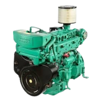
Presentation D5A T HE The D5A T HE is a turbocharged, in-line, direct injection, 4-cylinder, 4-stroke marine genset. It is equipped with an engine mounted heat exchanger suitable for rawwater cooling or connection to a central cooling system. An optimal combination of combustion chambers, fuel injection system, and effective turbocharger, provide excel- lent fuel consumption over the whole range of power output. -
Page 13: D5A Ta He
Presentation D5A TA HE The D5A T HE is a turbocharged, aftercooled, in-line, direct injection, 4-cylinder, 4-stroke marine genset. It is equipped with an engine mounted heat exchanger suitable for rawwater cooling or connection to a central cooling system. An optimal combination of combustion chambers, fuel injection system, effective turbocharger and charge air coo- ling, provide excellent fuel consumption over the whole range of power output. -
Page 14: D5A T Rc
D5A T RC The D5A T RC is an in-line, direct injection, 4-cylinder, 4-stroke marine diesel engine. It has a turbocharger and is equipped with radiator cooling. An optimal combination of combustion chambers, fuel injection system, effective turbocharger and charge air coo- ling, provide excellent fuel consumption over the whole range of power output. -
Page 15: D5A T Kc (1-Circuit)
Presentation D5A T KC (1-circuit) The D5A T KC is a turbocharged, in-line, direct injection, 6-cylinder, 4-stroke marine genset. It is fitted with con- nections for keel cooling. An optimal combination of combustion chambers, fuel injection system, effective turbocharger and charge air coo- ling, provide excellent fuel consumption over the whole range of power output. -
Page 16: D5A Ta Kc (1½-Circuit)
Presentation D5A TA KC (1½-circuit) The D5A TA KC is a turbocharged, aftercooled, in-line, direct injection, 4-cylinder, 4-stroke marine genset. It is fit- ted with connections for 1-circuit keel cooling. An optimal combination of combustion chambers, fuel injection system, effective turbocharger and charge air cooling, provide excellent fuel consumption over the whole range of power output. -
Page 17: D5A Ta Kc (2-Circuit)
Presentation D5A TA KC (2-circuit) The D5A TA KC is a turbocharged, aftercooled, in-line, direct injection, 4-cylinder, 4-stroke marine genset. It is fit- ted with connections for 2-circuit keel cooling. An optimal combination of combustion chambers, fuel injection system, effective turbocharger and charge air cooling, provide excellent fuel consumption over the whole range of power output. -
Page 18: New Genset Initial Service
New genset initial service General Before starting a new or reconditioned genset for the first time, give it an initial inspection. This to guarantee your own safety as well as the maximum service life of the genset. External inspection Electrical wiring 1. -
Page 19: Starting
Starting Before starting WARNING! Before starting the genset make sure that neither people, nor tools, are in contact with moving parts of the engine or the generator. Notify the people in the vicinity of the genset when starting. WARNING! Make sure that you know how to stop the genset before you start it (in case of emergency). If you are starting the genset for the first time, be prepared to stop the engine immediately in case abnormal noise should occur during start up. - Page 20 Starting Start using auxiliary batteries WARNING! Ventilate well. Batteries generate oxyhydrogen gas, which is extremely flammable and explosive. A short circuit, naked flame or spark can cause a powerful explosion. Never reverse the polarity of the battery. Risk of sparks and explosion. 1.
-
Page 21: Marine Commercial Control
Control System Marine Commercial Control This chapter describes functions and operation of the Marine Commercial Control system (MCC) and the MCU (Marine Control Unit). Applications and Modes The MCC system can be configured for different applications. Auxiliary (AUX), Emergency (EME), Combined (CMB) and Propulsion (PRP). -
Page 22: Mcc System Overview
Control System MCC system overview Terminology MCC ............Marine Commercial Control, name of the over all system. MCU ............Marine Control Unit, the central control unit of the system. SDU ............Shutdown Unit, for engine protection. Activates a fuel shut-off valve to shut down the engine. -
Page 23: Mcu Panel Layout
Control System MCU Panel layout 1. LCD display 7. LED - Engine running 2. Horn reset (stops sound alarm) 8. Up button (Select and Increase) 3. Mode Left, toggles modes backwards 9. Down button (Select and Decrease) [Off - AUX(EME,HRB)] 10. - Page 24 Control System Info view Serial number and software revision In MAIN page (A1), press and hold ENTER while pres- sing PAGE. INFO view with serial number an software revision will appear. NOTE! INFO view is only displayed for 10 seconds. MCU adjustments Backlight - INFO view In INFO view, press and hold ENTER and adjust...
- Page 25 Control System Operational modes Local mode In Local Mode the MCU is operational only from the main panel. All external interfaces are disabled. Local mode is activated by pressing ENTER + MODE- Right buttons. Local mode is deactivated by pressing ENTER + MODE- Left buttons.
-
Page 26: Menus
Control System Menus There are 4 display menus available: Main Measurement Adjustment History Main Press PAGE button to toggle the menu screens. Se- lect MAIN page (A1). Use UP/DOWN buttons to togg- le the different screens. Alarm list ECU (Engine Control Unit) alarm list and Alarm list are the last two screens in the MAIN page (A1). - Page 27 Control System Statistic values can be adjusted from PC software (password protected), contact your Volvo Penta dea- ler. Measurement Press PAGE button repeatedly to toggle the menu screens. Select MEASUREMENT view (B1). Use UP/ DOWN buttons to toggle the different screens.
-
Page 28: Operation
Control System Operation Starting the engine 1. In MAIN menu, select mode of operation (AUX, HRB, EME), refer to section ”Applications & Modes”), using MODE button (left or right)(A). 2. Make sure engine status is ”Ready”(B). 3. Press START button and the engine state should change to ”Running”(C). -
Page 29: Mcu Menu Flow Chart
Control System MCU menu flow chart... - Page 30 Changing setpoints concerning MCU telematics func- successful start, etc. tionality. NOTE! Telematics functionality is not supported by A10. Volvo Penta. Refer to http://www.huegli-tech.com Will always be empty. A11. Page or changing date and time. Displays alarms from the Shutdown system (SDU) and MCU.
-
Page 31: Setpoints
Control System Setpoints Below is a list of setpoints used in the system. The setpoints are grouped as: - Basic settings - Engine parameters - Engine protection settings - Active calls/SMS settings - Date/Time settings This is how they appear in the MCU menu. Note! An ”N”... -
Page 32: Shutdown System Overview
Shutdown system overview Shutdown unit (SDU) Overspeed shutdown The SDU has 6 shutdown channels and one over- The overspeed function shuts down the engine in speed shutdown. case of overspeed. S1 Cooling water temp Overspeed test S2 Lube oil pressure, Marine Gear To test the overspeed function push the overspeed test button (inside the SDU). -
Page 33: Sdu Indications
SDU indications 1. Green – Power A. Broken wire reset button 2. Red – Overspeed Alarm B. Yellow – Fuel valve Broken wire detected 3. Yellow – Run detection S4 C. Yellow – Speed sender Broken wire detected 4. Green – Run detection S2, S3 D. -
Page 34: Operation
Operation General Learn how to handle the engine, controls and other equipment in a safe and correct manner before starting the engine WARNING! Stay clear of all rotating and moving WARNING! A hot engine may cause burns. parts during operation. Beware of hot surfaces. -
Page 35: Stopping
Stopping Allow the engine to run at no load for a couple of minutes before turning it off. This will keep the engine temperatu- re in balance and prevent it from boiling. IMPORTANT! The procedure described above is IMPORTANT! If the engine stops abnormally, try especially important if the enginehas been run at to locate the problem and make the repairs heavy loads. -
Page 36: Anti-Freezing Measures
Stopping the engine Anti-freezing measures If the engine room cannot be protected from frost, the raw water system must be drained (if it contains sea water) and the coolant in the freshwater system must contain the right mix of anti-freeze and water. Refer to chapter Maintenance “Raw water system”... -
Page 37: Maintenance
Volvo Penta recommends that accurate maintenance records are kept. With accurate maintenance records your Volvo Penta Dealer can help in fine tuning the recommended service intervals to meet the specific operating situ- ation. This should result in a lower engine operation cost. -
Page 38: Recommendation Of Daily Operation Records
Maintenance: General Recommendation of Daily Operation Records Daily recording is a preventive maintenance program and when comparing values with engine history it will help you recognize conditions, signs or indications of approaching trouble. Daily operation records also make trouble shooting easier and will lessen the down time (to save time and money for servicing). Items to be recorded The following items are recommended to be recorded once a day:... -
Page 39: Maintenance Schedule
Change lubrication oil filters ..............(refer to note 4) Check the manometer(valid only for twin filters) and change filter if necessary. To be carried out at an authorized Volvo Penta workshop. Oil change intervals vary, depending on oil grade and sulphur content of the fuel. Refer to chapter ”Technical Data Lubrication oil specification”... - Page 40 Change coolant Check the manometer and change filter if necessary. To be carried out at an authorized Volvo Penta workshop. Oil change intervals vary, depending on oil grade and sulphur content of the fuel. Refer to chapter ”Technical Data Lubrication oil specification”...
-
Page 41: Engine
Maintenance: Engine Engine Drive belts Check belt tension and condition regularly. Check and adjust belt tension after operation when the belt is warm. IMPORTANT! Always change worn or cracked belts (belts working in pairs must be replaced together). IMPORTANT! If the belt is too taut it can damage bearings and/or pump and a too loose belt may slip. -
Page 42: Valve Clearance
Maintenance: Engine Changing 1. Remove the belt for the fuel pump. 2. Loosen screw (5) and push the alternator belt pulley (4) to the left and remove the belt. 3. Replace it with a new one. 4. Push the alternator belt pulley (4) to the right until the correct belt tension is achieved, tighten the screw (5). - Page 43 Maintenance: Engine Crankshaft position 1: • Turn crankshaft until both valves in cylinder 1 overlap (exhaust valve about to close, inlet valve about to open). • Adjust clearance of valves marked in black on schematic. • Mark respective rocker arm with chalk to show that adjustment has been carried out.
-
Page 44: Lubrication System
Maintenance: Lubrication system Lubrication system Checking oil level The oil level must be within the marked range on the dipstick and should be checked daily. Filling oil Top up the oil through the filler opening in the ventila- tion cover. Make sure the correct level is attained but wait a few minutes to allow the oil to run into the oil sump. -
Page 45: Changing Oil Filter
Maintenance: Lubrication system Changing oil filter Change the oil filter every second oil change. 1. Drain the oil, see section ”Changing oil”. 2. Put a vessel underneath the filter to avoid oil spill. 3. Unscrew the oil filters with a suitable filter wrench. 4. -
Page 46: Fuel System
Maintenance: Fuel System Fuel system Bleeding the fuel system The fuel system must be bled, e.g. after changing fuel filter, if the fuel tank has been run dry and after long stops. . 1. Put a suitable vessel under the fuel return (1). 2. -
Page 47: Fuel Pre-Filter/Water Separator
Maintenance: Fuel System Switchable fuel filters WARNING! Working on or approaching a running engine is a safety hazard. Beware of rotating parts and hot surfaces. 1. Place a receptacle beneath the filters and carefully clean the filter bracket. 2. Put the lever (2) in its right-hand end position. 3. - Page 48 Maintenance: Fuel System Twin fuel pre-filter/water separator The twin filter is equipped with a pressure gauge (1). The filter inserts must be changed according to the maintenance schedule or earlier if the pressure gauge indicates a vacuum of 6–10 inHg at no load or 16–20 inHg at full load.
-
Page 49: Air Inlet And Exhaust Systems
Maintenance: Air Inlet and Exhaust system Air inlet and exhaust systems Changing air filter Replace the air filter when the red field in the service indicator is fully visible when the engine is stopped. 1. Undo the hose clamp below the air filter cartridge and pull off the cartridge. -
Page 50: Cooling System, General
It cools the internal cooling system in an engine mounted or externally mounted heat exchanger. The Volvo Penta Genset comes with an internal freshwater system connected to an engine mounted heat exchan- ger, a radiator cooler, or prepared for external cooling, e.g. keel cooling or central cooling. - Page 51 Maintenance: Cooling system general Cooling system D5A T HE The system includes two circuits. The freshwater system is cooling the cylinder liners and the cylinder heads. An engine driven cooling water pump circulates the coolant through the heat exchanger and through the engine. The rawwater system is cooling the coolant in the freshwater cooling system.
- Page 52 Maintenance: Cooling system general Cooling system D5A TA HE The system includes two circuits. The freshwater system is cooling the charge air, the cylinder liners and the cy- linder heads. An engine driven cooling water pump circulates the coolant through the heat exchanger and through the engine.
- Page 53 Maintenance: Cooling system general Cooling system D5A T RC The engine cooling water is cooled by a radiator in a one-circuit cooling system. Air is forced through the radiator by an engine driven cooling air fan. The charge air is cooled in an air-to-air charge air cooler mounted in front of the radiator and it make use of the air flow from the engines cooling fan before it enters the radiator.
- Page 54 Maintenance: Cooling system general Cooling system D5A T KC (1-circuit) The engine cooling water (freshwater) is cooled by, e.g, a box cooler, a grid cooler, or any other external heat ex- changer. The system is cooling the cylinder liners and the cylinder heads. An engine driven freshwater pump cir- culate the coolant through the engine.
- Page 55 Maintenance: Cooling system general Cooling system D5A TA KC (1½-circuit) The engine cooling water is cooled by, e.g, a box cooler, a grid cooler, or any other external heat exchanger. When the coolant temperature in the HT-circuit is too high the thermostat valve opens and allows water of a lower temperature from the LT-circuit to enter the HT-circuit.
- Page 56 Maintenance: Cooling system general Cooling system D5A TA KC (2-circuit) The engine cooling water is cooled by, e.g, a box cooler, a grid cooler, or any other external heat exchanger. The HT-circuit is cooling the cylinder liners, the cylinder heads, and the lubrication oil.. An engine driven HT-pump circulates the coolant through the engine.
-
Page 57: Freshwater System
Maintenance: Freshwater system Freshwater system Checking coolant level WARNING! Never open the pressure cap when the engine is warm. Steam or hot fluid may spurt out. Stop the engine and allow it to cool. When engine is cold the coolant level must be visible at the lower edge of the filler neck on the expansion tank. -
Page 58: Draining The Coolant
Maintenance: Freshwater system Draining the coolant WARNING! Stop the engine and allow it to cool down before draining. Hot coolant and hot surfaces can cause burns. WARNING! Glycol is a health hazard (poison). Collect the old coolant and leave it to a destruc- tion plant. -
Page 59: Rawwater System
Maintenance: Rawwater system Rawwater system WARNING! The rawwater system (LT-Circuit) must be closed and drained before commencing work on the system. This due to the risk of seawater or water from the central cooling system entering the vessel. Draining the rawwater system (LT-circuit) 1. -
Page 60: Rawwater Pump (Lt-Pump)
Maintenance: Rawwater system Rawwater pump (LT-pump) Disassembly 1. Drain the water from theraw water system. 2. Remove the coolant pipes to and from the raw wa- ter pump. 3. Remove the connecting socket. 4. Remove the screw cap. 5. Remove the hex nut from the gear. 6. -
Page 61: Engine Mounted Heat Exchanger
Maintenance: Rawwater system Engine mounted heat exchanger (HE-engines only) 1. Loosen screws (1). 2. Remove the reverse cover (2) and on the rear side the connecting cover (3). 3. Gently drive out the raw water bundle (4). 4. Clean the raw water bundle and the heat exchanger housing (5). -
Page 62: Electrical System
Checking the electrical wiring Make sure electrical connections are tightened, dry and free from oxide. If necessary, spray these con- nections with water-repellant (Volvo Penta all-round oil). Main switches The main switches must never be turned off until the engine has been stopped. -
Page 63: Battery Maintenance
Maintenance: Electrical system Battery maintenance WARNING! Risk for fire and explosion. Never expose the battery to naked flames or sparks. WARNING! Never reverse the polarity of the battery. Risk of sparks and explosion. WARNING! Battery electrolyte is extremely corrosive. Protect eyes, skin and clothes when handling batteries. - Page 64 Maintenance: Electrical system Battery charging WARNING! Risk for explosion. Charging generates hydrogen gas (oxyhydrogen gas). A short circuit, naked flame or spark can cause a powerful explosion. Ventilate well. WARNING! Battery electrolyte is extremely corrosive. Protect eyes, skin and clothes. Always use protective goggles and gloves.
-
Page 65: Inhibiting
Before taking the genset out of service for long periods, it should be checked by a Volvo Penta dealer for possible need of overhaul or repair. WARNING! Certain preservatives are flammable. Some are also dangerous to inhale. Provide good venti- lation. - Page 66 Inhibiting Return the engine to service 7. Check the coolant level and anti-freeze. Top up if 1. Remove any protective covers on the engine, air necessary. intake and exhaust pipe. 8. Check under and around the engine for such items 2.
-
Page 67: Troubleshooting
A number of symptoms and possible causes for engine disturbances are described in the table below. For genera- tor specific troubleshooting, refer to generator documentation. If faults or hitches arise that you cannot solve alo- ne, you must always get in touch with your Volvo Penta dealer. Symptoms and possible causes... -
Page 68: Technical Data
Technical Data D5A T HE General Number of cylinders ..........Displacement ............4,76 liters (290 in Valve clearance (cold engine): inlet ................ 0,30 mm (0,0118’’) exhaust ..............0,50 mm (0,0197’’) Compression pressure at starter motor speed (120 rpm) ......not available Dry Weight*, engine with, without generator and frame, approx. -
Page 69: D5A Ta He
Technical Data D5A TA HE General Number of cylinders ..........Displacement ............4,76 liters (290 in Valve clearance (cold engine): inlet ................ 0,30 mm (0,0118’’) exhaust ..............0,50 mm (0,0197’’) Compression pressure at starter motor speed (120 rpm) ......not available Dry Weight*, engine, without generator and frame, approx. -
Page 70: D5A T Rc
Technical Data D5A T RC General Number of cylinders ..........Displacement ............4,76 liters (290 in Valve clearance (cold engine): inlet ................ 0,30 mm (0,0118’’) exhaust ..............0,50 mm (0,0197’’) Compression pressure at starter motor speed (120 rpm) ......not available Dry Weight*, engine with heat exchanger, without generator and frame, approx. -
Page 71: D5A T Kc (1-Circuit)
Technical Data D5A T KC (1-circuit) General Number of cylinders ..........Displacement ............4,76 liters (290 in Valve clearance (cold engine): inlet ................ 0,30 mm (0,0118’’) exhaust ..............0,50 mm (0,0197’’) Compression pressure at starter motor speed (120 rpm) ...... -
Page 72: D5A Ta Kc (1½-Circuit)
Technical Data D5A TA KC (1½-circuit) General Number of cylinders ..........Displacement ............4,76 liters (290 in Valve clearance (cold engine): inlet ................ 0,30 mm (0,0118’’) exhaust ..............0,50 mm (0,0197’’) Compression pressure at starter motor speed (120 rpm) ......not available Dry Weight*, engine, without generator and frame, approx. -
Page 73: D5A Ta Kc (2-Circuit)
Technical Data D5A TA KC (2-circuit) General Number of cylinders ..........Displacement ............4,76 liters (290 in Valve clearance (cold engine): inlet ................ 0,30 mm (0,0118’’) exhaust ..............0,50 mm (0,0197’’) Compression pressure at starter motor speed (120 rpm) ......not available Dry Weight*, engine, without generator and frame, approx. -
Page 74: Fuel Specification
Technical Data Fuel specification Fuel must comply with national and international standards at the least, e.g.: JIS KK 2204....... Type1, Type2, Type3 ASTM, D975 ........No.1-D, No.2-D EN590 ......with national environment and cold requirements Note! It is necessary to use a fuel that has a pour point suitable for ambient temperature during the operation of the engine. -
Page 75: Lubrication Oil Specification
Technical Data Lubrication oil specification Recommended types of engine oil Important! Use of improper or inferior oil can cause excessive wear of bearings and moving parts, thus shortening the engine life. It can also result in sticking of piston rings and seizing of pistons in the cylinders, thus causing major damage. -
Page 76: Coolant Specification
The mixture of Volvo Penta Coolant and water should contain 40-55% Volvo Penta Coolant. If the coolant contains less than 40% Volvo Penta Coolant, the cooling galleries in the engine or radiator may be blocked by contamination. If the coolant contains more than 60% Volvo Penta Coolant the cooling ability of the coolant mixture is impaired, this may cause the engine to overheat. -
Page 77: Identification Numbers
Technical Data Identification numbers Type plates with identification numbers can be found on the engine and the generator. This information must al- ways be used as a reference when ordering service and spare parts. Engine Type Plate(1) Generator plate (3) 1. -
Page 78: Notes
Notes ........................................................................................................................................................................................................................................................................................................................................................................................................................................................................................................................................................................................................................................................................................................................................................................................................................................................ - Page 79 ........................................................................................................................................................................................................................................................................................................................................................................................................................................................................................................................................................................................................................................................................................................................................................................................................................................................................................................................................................................
- Page 80 .............................................................................................................................................................................................................................................................................................................................................................................................................................................................................................................................................................................................................................................................................................................................................................................................................................................................................................
Need help?
Do you have a question about the D5A T and is the answer not in the manual?
Questions and answers