
Related Manuals for EM Acoustics EMS-156


Summary of Contents for EM Acoustics EMS-156
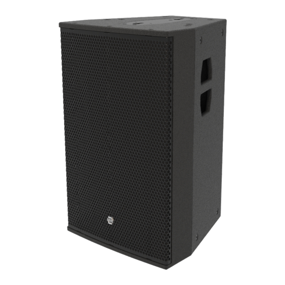
- Page 1 EMS-156 / 159 two-way passive fullrange loudspeaker Product User Manual v2 November 2019 L O U D S P E A K E R S D E F I N E D...
-
Page 2: Table Of Contents
DECLARATION OF CONFORMITY ........................ 4 1.0 - Introduction ............................. 5 Unpacking............................... 5 2.0 – EMS-159/156 & Accessories ......................6 EMS-159 ................................. 6 EMS-156 ................................. 6 FC-159h ................................7 FC-159v ................................7 VFA-159 ................................. 7 CM-159 ................................8 2.1 – Rotating the HF waveguide ......................8 NOTE: Be careful not to over-rotate the waveguide in one particular direction to avoid over-tensioning the cables. - Page 3 7.2 – EMS-159: Removing the LF drive unit .................. 25 7.3 – EMS-159: Removing the HF drive unit ................. 26 Appendix A – Technical Specifications ....................27 EMS-156/EMS-159 passive fullrange loudspeaker ..............27 Appendix B – Technical Drawings ......................28 Appendix C – Spare Parts List ........................32 Appendix D –...
-
Page 4: Declaration Of Conformity
Page 4 of 33 DECLARATION OF CONFORMITY The products contained within this manual conform to the requirements of the EMC Directive 89/336/EEC, amended by 92/31/EEC and to the requirements of the Low Voltage Directive 73/23/EEC amended by 93/68/EEC. EMC Emission EN55103-1:1996 Immunity EN55103-2:1996... -
Page 5: Introduction
- 90° x 60° for the EMS-159, and 60° x 40° for the EMS-156. These two drive units are linked with an extremely comprehensive passive crossover network. This means the EMS-159 exhibits flat frequency and phase responses without the need of external corrective processing. -
Page 6: Ems-159/156 & Accessories
2.0 – EMS-159/156 & Accessories EMS-159 Compact passive loudspeaker FEATURES & BENEFITS • Signature EM Acoustics “maximum headroom” design approach ensures consistency of performance regardless of SPL level. • Quick-release “keyhole” flying plates for swift attachment of primary rigging accessories. -
Page 7: Vfa-159
Page 7 of 33 FC-159h The FC-159h is a simple and effective means of mounting the EMS-159 in both Horizontal flying cradle temporary and permanent applications. It is secured to the cabinet by means of M10 socket head bolts into the top and bottom of the loudspeaker to mount it in a landscape format. -
Page 8: Rotating The Hf Waveguide
By default, the EMS-159 ships from the factory with the dispersion pattern 90° horizontal x 60° vertical when the loudspeaker is in a portrait format (60° horizontal x 40° vertical for the EMS-156). To rotate the waveguide: 1. Follow step 1 in the servicing chapter (Chapter 7) to remove the grille. -
Page 9: Simulation
Windows (XP or Higher) only. It can also be downloaded directly from the EM Acoustics website with all the current product files embedded. Tutorials for Ease Focus 3 are available from with the application itself. -
Page 10: Safety Considerations
General Considerations in use Loudspeaker systems are potentially dangerous objects if used incorrectly. Please ensure that you read this section fully, and contact EM Acoustics or your local dealer should you be in any doubt over correct operation procedures. Personal Injury Never stand in the immediate vicinity of loudspeakers when in use at high level. -
Page 11: Ground Stacking
EM Acoustics loudspeaker product (unless where specifically stated) or any other loudspeaker system. The use of EM Acoustics accessories with other manufacturers’ systems may compromise the safety standards and EM Acoustics is in no way liable for any loss, damage or injury caused by such practice. -
Page 12: Secondary Safeties
In most cases, annual independent tests & inspections carried out by a suitably approved and qualified inspector will be required. EM Acoustics recommends detailed logbooks be kept of all inspections and load tests to ensure an accurate record is kept of the testing for each EM Acoustics rigging accessory. -
Page 13: Rigging & Mounting Options
Page 13 of 33 5.0 – Rigging & Mounting Options 5.1 – EMS-159 Cabinet Overview M10 Form A (flat) washer M10 spring washer M10x20 socket bolt Top keyhole location point Locking pin location Top M10 threaded flying point Carrying handle Bottom keyhole location point Bottom M10 threaded flying point Rear M8 safety point... -
Page 14: Using The Fc-159V
Page 14 of 33 5.2 – Using the FC-159v The FC-159v is intended to mount the EMS-159 vertically – either using a hook clamp or similar from above. Firstly, assemble the mounting plate to the inner yoke as per the instructions supplied with the FC-159v. -
Page 15: Fc-159V Angle Setting
Page 15 of 33 5.2.1 – FC-159v Angle Setting The holes on the pivots of the FC-159v allow quick and repeatable angle setting when in use, and the pins provide a secondary means of ensuring the angle remains set. HOLE A: 0° + (n x 20°) down-tilt HOLE B: 10°... -
Page 16: Using The Fc-159H
Page 16 of 33 5.3 – Using the FC-159h The FC-159h is intended to mount the EMS-159 horizontally. To fit, lie the EMS-159 on its side and loosen the locking knobs so that the mounting plates can be rotated to allow access to the mounting bolt holes. -
Page 17: Using The Vfa-159
Page 17 of 33 5.4 – Using the VFA-159 The VFA-159 is designed to suspend the EMS-159 from a single point, using the centre of gravity of the loudspeaker to determine the up or down tilt angles. A moveable pickup point allows setting of the angle in 5-degree increments from +25°... -
Page 18: Use With The Cm-159 Column Mount
Page 18 of 33 5.5 – Use with the CM-159 column mount The CM-159 is intended to allow other loudspeakers to be swiftly and safely mounted below a flown EMS-159. The CM-159 attaches to the underside of the EMS-159 in exactly the same way as the FC-159v or VFA-159 –... -
Page 19: Powering The System
Page 19 of 33 6.0 – Powering the System The EMS-159 can be powered from any amplifier & DSP combinations with the relevant high & low pass filter, and limiter settings. However, due to the self-contained nature of the package, the use of DQ Series advanced system amplifiers is highly recommended. The use of DQ Series amplifiers provides a neat and flexible system that will encompass all requirements for the system to function correctly, as well as providing user control for room EQ and system alignment. -
Page 20: Amplifier Requirements
If not using DQ Series amplifiers, or the DSC48 Digital System Controller, then a suitable DSP system must be used in conjunction with your EMS-159 to prevent damage to the loudspeaker. Check the EM Acoustics website for the most up-to-date DSP settings for the EMS-159. -
Page 21: Presets And Settings
Page 21 of 33 6.2 - Presets and Settings 6.2.1 – Standard EMS-159 Preset When used with a DQ Series amplifier EMS-159 loudspeakers require only a single amplifier channel, and as such the preset recalled will only require one output from your DQ Series amplifier. -
Page 22: Use With The Dq Series Advanced System Amplifiers
EMS-159.full Standard EMS-159 preset EMS-156.full Standard EMS-156 preset As mentioned above, these presets are intended to be a starting point and additional work may be required depending on the venue, the style of content and the end result you are looking for. -
Page 23: System Connectivity
Because pins 2+/2- are linked through inside all EM Acoustics loudspeakers, using a 4-core cable to one loudspeaker (carrying two different signals) allows a crossover cable to be used to link out of the first loudspeaker into another, thereby feeding it from a separate signal. -
Page 24: Servicing Information
Page 24 of 33 7.0 – Servicing Information All EMS-159 components can be removed for service purposes if required, using the minimum of tools. 7.1 – EMS-159: Removing the grille TOOLS REQUIRED: 4mm Allen key Lie the enclosure on its’ back and remove the three M6x30 countersunk socket screws from each end using a 4mm Allen key, and then lift the grille clear of the cabinet. -
Page 25: Ems-159: Removing The Lf Drive Unit
Page 25 of 33 7.2 – EMS-159: Removing the LF drive unit TOOLS REQUIRED: 5mm Allen key Complete step 7.1 above to remove the grille. Using a 5mm Allen key, remove the two M6x55 socket cap screws that secure the brace in front of the drive unit. -
Page 26: Ems-159: Removing The Hf Drive Unit
Page 26 of 33 7.3 – EMS-159: Removing the HF drive unit Complete step 7.1 above to remove the grille. Using a 4mm Allen key, remove the eight M6x40 countersunk socket screws that secure the waveguide. M6x40 countersunk socket screws Lift the drive unit clear of the baffle and disconnect the cables –... -
Page 27: Appendix A - Technical Specifications
Net/Shipping Weight: 43/45kg (94.6/99lbs) Frequency Response (+/- 3dB) 65Hz – 20kHz Dispersion 60° x 40° (EMS-156), rotatable 90° x 60° (EMS-159), rotatable Drive Units: 15” (381mm) neodymium LF drive unit 1.4” (36mm) exit neodymium HF compression drive unit Power Handling:... -
Page 28: Appendix B - Technical Drawings
Page 28 of 33 Appendix B – Technical Drawings EMS-159 User Manual v1 November 2019... - Page 29 Page 29 of 33 EMS-159 User Manual v1 November 2019...
- Page 30 Page 30 of 33 EMS-159 User Manual v1 November 2019...
- Page 31 Page 31 of 33 EMS-159 User Manual v1 November 2019...
-
Page 32: Appendix C - Spare Parts List
DU-1505 replacement 15” neodymium LF drive unit 01B014 CDU-1404 replacement 1.4” neodymium HF compression drive unit 04A064 RFG-159 replacement grille/fabric for EMS-159 07A034 PX-156 replacement passive crossover assembly for EMS-156 07A035 PX-159 replacement passive crossover assembly for EMS-159 EMS-159 User Manual v1 November 2019... -
Page 33: Appendix D - Warranty Information
Serial numbers must be quoted in all correspondence relating to the claim. EM Acoustics or its representatives are in no way liable for any loss or damage in transit, and hence it is recommended that the sender insure the shipment. EM Acoustics will pay for return freight should the repair be covered under warranty.
Need help?
Do you have a question about the EMS-156 and is the answer not in the manual?
Questions and answers