Table of Contents
Advertisement
Quick Links
Advertisement
Table of Contents

Related Manuals for Wachendorff URDR001A


Summary of Contents for Wachendorff URDR001A
- Page 1 URDR001A Controller User manual...
- Page 2 2 - URDR001A - User manual...
-
Page 3: Table Of Contents
Configuration through memory card ....................25 9.2 Memory card creation/update........................26 9.3 Configuration loading from memory card ..................26 10 Loading default values .............................26 11 Access configuration ..............................26 11.1 Parameters list functioning ........................27 12 Table of configuration parameters ........................27 3 - URDR001A - User manual... - Page 4 13.g Upper deviation alarm (par. 123 ) ..................53 AL. 1 .F. up.dev. 13.h Lower deviation alarm (par. 123 ) ..................53 AL. 1 .F. Lo.dev. 13.1 Alarms label ..............................53 14 Fault reporting table ..............................54 4 - URDR001A - User manual...
-
Page 5: Safety Guidelines
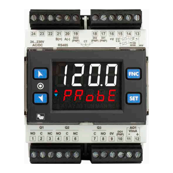
Introduction The process controller URDR001A is specifically conceived for application on control panels with DIN rail mounting. It stands out for the bright display which ensures optimal visibility and increased level of information for the operator beside a scrolling help function. -
Page 6: Precautions For Safe Use
• Not suitable for Class 2 wiring methods • Not intended for connection to Class 2 equipment • Secure current transformer and route conductors so that the conductors do not directly contact live terminals or bus. 6 - URDR001A - User manual... -
Page 7: Environmental Policy / Weee
P, PI, PID, PD with proportional time Proportional band 0..9999°C o °F Integral time 0,0..999,9 sec (0 excludes) Derivative time 0,0..999,9 sec (0 excludes) Manual or automatic Tuning, selectable alarm, protection of command Controller functions and alarm setpoints. 7 - URDR001A - User manual... -
Page 8: Programming Mode
When activated by a reader/interrogator supporting NFC-V protocol, Wachendorff EMG-App controller URDR001A is to be considered a VICC (Vicinity Inductively Coupled Card) according to ISO/IEC 15693 and it operates at a frequency of 13.56 MHz. The device does not intentionally emit radio waves. -
Page 9: Wiring Diagram
• When shielded cable is used, it should be grounded at one side only to avoid ground loop currents. AI1 V mA • It’s possible to select +V at 12Vdc or 24Vdc, by configuring parameter 282 (GROUP R - - Display and interface). V.out diSP. Shield/Schermo 9 - URDR001A - User manual... -
Page 10: Ct Input
Capacity 5 A (3 A for Q2) / 250 VAC for resistive loads. 220V 220V See chart below. Electrical endurance Q1, Q2: • 5 A (3 A for Q2), 250 VAC, resistive loads, 10 operations. • 20/2 A, 250 VAC, cosφ = 0.3, 1.2x10 operations. 10 - URDR001A - User manual... -
Page 11: Relay Output Q3
ON when alarm 3 is active. ON when the controller is executing an auto-tuning cycle. ON when “Manual” function is active. ON when the controller communicates through serial. Flashes when the remote setpoint is enabled. 11 - URDR001A - User manual... -
Page 12: Keys
• Running Tuning by serial input: Write 1 on word modbus 1216 (command 1) or 1217 (command 2): led switches ON and the procedure starts. Write 0 to stop the tuning. 12 - URDR001A - User manual... -
Page 13: Tuning Once
• : DRR244 execute a cooling type regulation with digital input active, otherwise the regulation Act.ty. is of heating type; 13 - URDR001A - User manual... -
Page 14: Digital Input Functions
PID immediately before breakage. Ex: on an extruder the command in percentage of the resistance (load) is maintained also in case of input sensor failure. 14 - URDR001A - User manual... -
Page 15: Heater Break Alarm On Ct (Current Transformer)
= 0 e = 0. i.t. 1 d.t. 1 x = COOL < 0 (HEAT) ACTIVE COMMAND OUTPUT (HEAT) ACTIVE ALARM OUTPUT (COOL) x = COOL 15 - URDR001A - User manual = 0... -
Page 16: Latch On Function
Set virtual zero. Display shows zero. If “Virtual zero at start”is selected, point 4 To exit procedure press SET. must be repeated at each starting. 1 The tuning procedure starts by exiting the configuration after changing the parameter. 16 - URDR001A - User manual... -
Page 17: Soft-Start Function
(“Retransmission 1”) the value to be retransmitted and on parameter 299 rtM. 1 (“Retransmission 1 Type”) the output type. r. 1 .tY. It is possible also to select on parameters 300 and 301 the input value rescale limits. r. 1 .L.L. r. 1 .u.L. 17 - URDR001A - User manual... -
Page 18: Timer Functions
The proposed solutions are as follows: A.tM. 1 A.tM.2 Alarm active during timer counting Start Alarm active when the timer expiry Alarm active 5 “ before the timer expiry WArn. 18 - URDR001A - User manual... -
Page 19: Serial Communication
Serial communication URDR001A is equipped with RS485 and can receive/broadcast data via serial communication using MODBUS RTU protocol. The device can only be configured as a Slave. This function enables the control of multiple controllers connected to a supervisory system / SCADA. - Page 20 Bit0 = Digital inp. 1 Bit1 = Digital inp. 2 Outputs status (0=off, 1=on) Bit 0 = Q1 Bit 3 = DO1 1012 Bit 1 = Q2 Bit 4 = DO2 Bit 2 = Q3 20 - URDR001A - User manual...
- Page 21 R/W 0 1216 1=autotuning ON With synchronized Tune (par. 73 tun. 1 SYncH. 0=autotunig function OFF 1=command output OFF (forces the cooling) R/W 0 2=command output ON (forces the heating) 3=autotuning ON 4=autotuning ended 21 - URDR001A - User manual...
- Page 22 Alarm 2 lower setpoint if Par. 141 , with decimal point AL.2.F . A.band 1352 R/W EEPROM selection Alarm 3 lower setpoint if Par. 159 , with decimal point AL.3.F . A.band 1353 R/W EEPROM selection 22 - URDR001A - User manual...
-
Page 23: Serial Compatibility With Urdr0001
R/W EEPROM Serial compatibility with URDR0001 In existing plants where it is necessary to replace an URDR0001 it is possible to install a new URDR001A enabling the Modbus register’s compatibility. To enable the Modbus register’s compatibility with the URDR0001, simply enter the password 0243. - Page 24 * If value is 0, the control is disabled. If different from 0, it is the max. time which can elapse between two pollings before the controller goes off-line. If it goes off-line, the controller returns to Stop mode, the control output is disabled but the alarms are active. 24 - URDR001A - User manual...
-
Page 25: Reading And Configuration Through Nfc
• Identify the position of the NFC antenna on the smartphone (usually central, behind the back cover) or to one of the sides in case of metal chassis. The URDR001A’s antenna is placed on the frontal panel, under the function keys. -
Page 26: Memory Card Creation/Update
Confirms and stores the new value. If the value is different from default values, the arrow keys light on. Backs to parameter groups selection Press again to exit configuration (see point 3). 26 - URDR001A - User manual... -
Page 27: Parameters List Functioning
-40 °C..150 °C ntc 3 Decimal Point 1 d.P. 1 Select number of displayed decimal points for AI1 Default 1 decimale 2 decimali 0.00 3 decimali 0.000 Degree deGr. Celsius (Default) °C Fahrenheit °F Kelvin 27 - URDR001A - User manual... - Page 28 62.0 Hz 10.0Hz 62.0Hz 12.5 Hz 123 Hz 12.5Hz 123Hz 242 Hz 16.7 Hz (Default) Ideal for noises 242Hz 16. 7Hz 470 Hz (Max. speed conversion) filtering 50 / 60 Hz 470Hz 19.6 Hz 19.6Hz 28 - URDR001A - User manual...
- Page 29 Action type to control process 1. Heating (N.A.) (Default) HEAt Cooling (N.C.) cooL Command Hysteresis 1 c.HY. 1 Hysteresis to control process 1 in ON/OFF. -9999..+9999 [digit ] (degrees.tenths for temperature sensors). Default 0.2. 1 p. 54 29 - URDR001A - User manual...
- Page 30 Allows or not to modify command setpoint 1 value Modification allowed (Default) FrEE Protected Lock Free Initialized. At start, setpoint 1 of command 1 is initialized to the value set on FR.iN. parameter 51 (Initial Value Setpoint 1). i.SP .1 30 - URDR001A - User manual...
- Page 31 Proportional Band 1 p.b. 1 Proportional band or process 1 P.I.D. regulation (Process inertia). 0 ON / OFF if t.i. equal to 0 (Default) 1...10000 [digit ] (degrees.tenths for temp. sensors). 1 p. 54 31 - URDR001A - User manual...
- Page 32 Dead band combination for heating / cooling P.I.D. (double action) for process 1. -20.0%...50.0% Negative: Dead band. Positive: overlap. Default: 0.0% Cooling Cycle Time 1 c.c.t. 1 Cycle time for cooling output in heating / cooling P.I.D. mode for process 1. 1-300 seconds (Default:10 s) 32 - URDR001A - User manual...
- Page 33 Lev. 2 Lev. 5 (Default) Lev. 8 94÷97 Reserved Parameters - Group E Reserved parameters - Group E GROUP F - - Reserved res. 98÷122 Reserved Parameters - Group F Reserved parameters - Group F 33 - URDR001A - User manual...
- Page 34 ] (degrees for temp. sensors). Default 0.5. 1 p. 54 129 A. 1 .L.L. Alarm 1 Lower Limit Lower limit selectable for the alarm 1 setpoint. -9999..+30000 [digit ] (degrees for temp. sensors). Default 0. 1 p. 54 34 - URDR001A - User manual...
- Page 35 01 Message 16 (see table on paragraph 13.1) lb. 16 Custom message (modifiable by the user through the App or via modbus) user.l. 137÷140 Reserved Parameters - Group G Reserved parameters - Group G 35 - URDR001A - User manual...
- Page 36 ] (degrees for temp. sensors). Default 0.5. 1 p. 54 147 A.2.L.L. Alarm 2 Lower Limit Lower limit selectable for the alarm 2 setpoint. ] (degrees for temp. sensors). Default 0. -9999..+30000 [digit 1 p. 54 36 - URDR001A - User manual...
- Page 37 01 Message 20 (see table on paragraph 13.1) lb. 20 Custom message (modifiable by the user through the App or via modbus) user.l. 155÷158 Reserved Parameters - Group H Reserved parameters - Group H 37 - URDR001A - User manual...
- Page 38 Defines the output type if the alarm 3 is analogue. Output 0...10 V. Default 0.10 v Output 4...20 mA. 4.20ma 164 a.3.Hy. Alarm 3 Hysteresis Alarm 3 hysteresis. -9999..+9999 [digit ] (degrees for temp. sensors). Default 0.5. 1 p. 54 38 - URDR001A - User manual...
- Page 39 Positive value: delay when enter alarm status 171 A.3.S.p. Alarm 3 Setpoint Protection Allows or not to change the alarm 3 setpoint. Editable by the user (Default) FrEE Protected Lock Protected and not visualized HidE 39 - URDR001A - User manual...
- Page 40 (N.C. Threshold) Normally closed, active on reaching alarm 2 p. 54 n.c. tH. (N.O. Threshold Variation) disabled after changing control setpoint 3 p. 54 n.o.tH.V . (N.C. Threshold Variation) disabled after changing control setpoint 3 p. 54 n.c.tH.V . 40 - URDR001A - User manual...
- Page 41 Positive value: delay when enter alarm status 189 A. 4 .S.p. Alarm 4 Setpoint Protection Allows or not to change the alarm 4 setpoint. Editable by the user (Default) FrEE Protected Lock Protected and not visualized HidE 41 - URDR001A - User manual...
- Page 42 (N.C. Threshold) Normally closed, active on reaching alarm 2 p. 54 n.c. tH. (N.O. Threshold Variation) disabled after changing control setpoint 3 p. 54 n.o.tH.V . (N.C. Threshold Variation) disabled after changing control setpoint 3 p. 54 n.c.tH.V . 42 - URDR001A - User manual...
- Page 43 Positive value: delay when enter alarm status 207 A.5.S.p. Alarm 5 Setpoint Protection Allows or not to change the alarm 5 setpoint. Editable by the user (Default) FrEE Protected Lock Protected and not visualized HidE 43 - URDR001A - User manual...
- Page 44 232 d. i . 1 .c. Digital Input 1 Contact Defines the resting contact of the digital input 1. Normally open (Default) n.open Normally closed n.cLos. 233÷238 Reserved Parameters - Group M Reserved parameters - Group M 44 - URDR001A - User manual...
- Page 45 GROUP O - - Reserved res. 247÷254 Reserved Parameters - Group O Reserved parameters - Group O GROUP P - - Reserved res. 255÷262 Reserved Parameters - Group P Reserved parameters - Group P 45 - URDR001A - User manual...
- Page 46 The elapsed time is saved every 10 minutes. Initial waiting time disabled: the controller starts immediately (Default) hh.mm Initial waiting time enabled. 00:01-24:00 273÷276 Reserved Parameters - Group Q Reserved parameters - Group Q 46 - URDR001A - User manual...
- Page 47 Select the duration for the visualization of the user menu data, before returning to the default page. 3 seconds 1 minutes 1 MiN 5 minutes 5 seconds (Default) 5 MiN 10 minutes 10 seconds 10MiN 10 s Manual scroll 30 seconds MAn.Sc. 30 s 47 - URDR001A - User manual...
- Page 48 Alarm disabled. (Default) Ampere 0.1-200.0 292 H.b.a.d. Heater Break Alarm Delay Heater Break Alarm and overcurrent alarm activation delay. mm:ss (Default: 01:00) 00:00-60:00 293÷297 Reserved Parameters - Group S Reserved parameters - Group S 48 - URDR001A - User manual...
- Page 49 Selects slave address for serial communication. 1...254. Default: 247. 319 bd.rt. Baud Rate Selects baudrate for serial communication 1200 bit/s 1.2 k 2400 bit/s 2. 4 k 4800 bit/s 4.8 k 9600 bit/s 9.6 k 49 - URDR001A - User manual...
- Page 50 331 tmr.2 Timer 2 Enabling Timer 2 Disabled (Default) diSab. Enabled Enab. Enabled and active at start En.StA. 332 t.b.t.2 Time Base Timer 2 Selects time base for timer 2 minutes.seconds (Default) mm.SS hours.minutes hh.MM 50 - URDR001A - User manual...
-
Page 51: Alarm Intervention Modes
> 0). a. 1 .HY Time Alarm output Alarm Spv Hysteresis parameter Absolute alarm active below. < 0 Hysteresis value lower than “0” (Par. 128 < 0). a. 1 .HY Time Alarm output 51 - URDR001A - User manual... -
Page 52: Absolute Or Threshold Alarm Referred To Command Setpoint Active Over (Par. 123 = )
< 0 Alarm Spv H Command Spv Asymmetric band alarm with hysteresis value lower than “0” (Par. 128 < 0). Alarm Spv L a. 1 .HY Hysteresis parameter < 0 Time Alarm output 52 - URDR001A - User manual... -
Page 53: Upper Deviation Alarm (Par. 123 = )
By setting 0, no message will be displayed. While setting 21, the user will have up to 23 characters available to customize his message via the “MyPyxsys” App or via modbus. 53 - URDR001A - User manual... -
Page 54: Fault Reporting Table
3 Changing the control setpoint, the alarm will be disabled. It will stay disabled as long as the parameters that created it are active. It only works with deviation alarms, band alarms and absolute alarms (referring to the control setpoint). 54 - URDR001A - User manual... - Page 55 1 Integral Time 1 i.t. 1 Derivative Time 1 d.t. 1 Dead Band 1 d.b. 1 Proportional Band Centered 1 p.b.c. 1 Off Over Setpoint 1 o.o.s. 1 Off Deviation Threshold 1 o.d.t. 1 55 - URDR001A - User manual...
- Page 56 Alarm 2 Setpoint Protection A.2.S.p. Alarm 2 Label A.2.Lb. 155÷158 Reserved Parameters - Group H GROUP I - AL. 3 - Alarm 3 Alarm 3 Function AL.3.f. Reserved rEs. Reserved rEs. Alarm 3 State Output A.3.5.o. 56 - URDR001A - User manual...
- Page 57 Alarm 4 Setpoint Protection A. 4 .S.p. Alarm 4 Label A. 4 .Lb. 191÷194 Reserved Parameters - Group J GROUP K - AL. 5 - Allarme 5 (solo su URDR001A-13ABC e URDR001A-23XX-T) Alarm 5 Function AL.5.f. Reserved rEs. Reserved rEs.
- Page 58 1 . L.L. Retransmission 1 Upper Limit r. 1 . u.L. Retransmission 1 State Error r. 1 .s.e. 303÷307 Reserved Parameters - Group T GROUP U - res. - Reserved 308÷317 Reserved Parameters - Group U 58 - URDR001A - User manual...
- Page 59 1 Time Base Timer 1 t.b.t. 1 Action Timer 1 a.tm. 1 Timer 2 tmr.2 Time Base Timer 2 t.b.t.2 Action Timer 2 a.tm.2 Timers Sequence tMr.s. 335÷339 Reserved Parameters - Group W 59 - URDR001A - User manual...
- Page 60 Wachendorff Prozesstechnik GmbH & Co. KG Industriestrasse 7 • 65366 Geisenheim Tel.: +49 (0) 67 22 / 99 65 - 20 Fax: +49 (0) 67 22 / 99 65 - 78 E-Mail: wp@wachendorff.de www.wachendorff-prozesstechnik.de © Copyright by Wachendorff Prozesstechnik GmbH & Co. KG 2300.10.304-RevE 120723...
Need help?
Do you have a question about the URDR001A and is the answer not in the manual?
Questions and answers