Table of Contents
Advertisement
Advertisement
Table of Contents

Related Manuals for Wachendorff OPUS A6 ECO 2


Summary of Contents for Wachendorff OPUS A6 ECO 2
- Page 1 OPUS A6 2 Generation Operating Manual Hardware Description...
- Page 2 Operating Manual OPUS A6 2 Generation Order number: OPUSBA00A6G2 Wachendorff Elektronik GmbH & Co KG Industriestraße 7, 55411 Geisenheim, +49 6722 / 6722 4026-888 Supplements or a special operator manual may be required for customer-specific devices. Version 2.0, April 2016 All rights reserved, including translation.
-
Page 3: Table Of Contents
Dashboard Mounting Instruction for OPUS A6 2 Generation ........ 17 4.2.2 Dashboard Cut-out ...................... 18 4.2.3 Mounting Cover for OPUS A6 ECO 2 Generation ........... 19 4.2.4 Mounting Cover for OPUS A6 STANDARD 2 Generation ........20 Electrical installation OPUS A6 2 generation .............. - Page 4 Protection Level (IP Code) ..................29 5.4.3 Electrical Capability..................... 29 5.4.4 Mechanical Capability ....................29 5.4.5 Climate Capability ....................... 29 5.4.6 Chemical Capability..................... 30 Declaration of Conformity ....................31 5.5.1 Declaration of Conformity for OPUS A6 ECO 2 Generation ........31 Seite IV von 31...
-
Page 5: Preliminary Notes
Preliminary Notes Preliminary Notes This document is valid for the following OPUS A6 2 generation version: • OPUSA6E - “ECO” • OPUSA6S - “STANDARD” This document is directed to the qualified personnel and contains all the important information to the correct use of the OPUS A6 2 generation. -
Page 6: Safety Instructions, Guarantee And Liability
OPUS operator panel accordingly • have gained knowledge of the programming related concepts by education or trainings. Using the Projektor Tool a Projektor Tool training by Wachendorff needs to be attended. Using CoDeSys a CoDeSys training needs to be attended, either held by Wachendorff or 3S. -
Page 7: Power Supply
They are not allowed and lead to disclaimer of liability and guarantee exclusion. WACHENDORFF is not liable for damage that occurs due to improper misuse of the delivered components, or through failure to heed the instructions in the operating manual, including the safety instructions. -
Page 8: Nd Generation
WACHENDORFF is not liable for injuries to third party licenses for the contents used on OPUS panel by the end customer. Moreover we expressly declare that all obligations on the part of Wachendorff are exclusively derived from the respective purchase contract, in which the guarantee is conclusively stipulated. - Page 9 Safety instructions, guarantee and liability Unintentional operation Operating states can be called due to unintentional operation of the OPUS A6 2nd generation that are not appropriate for the situation. OPUS A6 2nd generation devices should be installed in such a manner that the possibility of unintentional operation is adequately excluded.
-
Page 10: Intended Use
Technical Documentation Intended Use The operator panel OPUS A6 2 generation is a programmable graphical display used to operate and monitor vehicles and working machines. The communication with other system components, as for example decentralised I/O module, occurs over the CAN interfaces with the supported protocols: CANopen, J1939 and CANfreestyle (layer 2). -
Page 11: Device Description
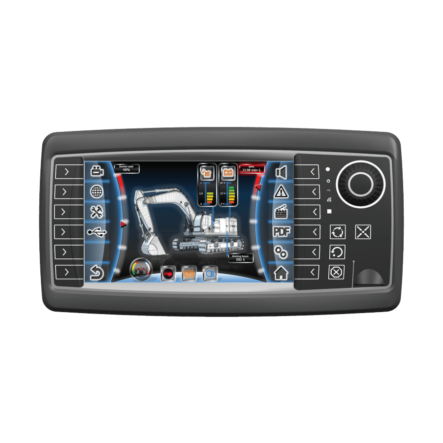
Lightsensor Status LEDs Multicolor LED Display Fig. 3.1: Schematic diagram of the OPUS A6 ECO 2 generation Display: 7” (800 x 480 px) TFT color graphic LCD display with capacitive touch. Light Sensor: The light sensor can be used for an automatic adaption of display-backlight and key- backlight to the ambient light intensity. - Page 12 Technical Documentation 3.2.2 OPUS A6 STANDARD 2nd generation Softkeys F1 – F12 Light sensor Status LEDs Multicolor LED Encoder Function Keys USB Slot behind flap Display Fig. 3.2: Schematic diagram of the OPUS A6 STANDARD Landscape 2 generation Display: 7” (800 x 480 px) TFT color graphic LCD display with capacitive touch. Softkeys F1 to F12: All softkeys can be assigned to the function defined in the customer specific application.
- Page 13 Technical Documentation value rotating the encoder. An entry function can be generated directly on rotating or by pressing the encoder. Light Sensor: The light sensor can be used for an automatic adaption of display-backlight and key- backlight to the ambient light intensity. Status LEDs: There are 2 different status LEDs available on the basic option unit and 3 status LEDs available on the full option unit:...
- Page 14 Technical Documentation Main connector: The following interfaces are available: Power supply and ignition input • 2 x CAN-Interfaces according to ISO/DIS 11898 • RS232-Interface • USB full speed • 4 configurable analogue/digital inputs (optional), where input 1 work with • frequency 1-10 kHz and may also be used as frequency input, inputs 2-4 works with max signal frequency of 50Hz 3 digital outputs (optional)
-
Page 15: Features Overview For Opus A6 2Nd Generation
1. Projektor-Tool: This powerful development environment provided by Wachendorff Elektronik GmbH & Co KG enables the quick and effective creation of an application for the OPUS A6 generation operator terminal. Use the Projektor to conveniently design the user interface on the computer, which can be easily displayed on the device. -
Page 16: Development Kit
It supports a download via USB stick and Ethernet. The Universal Downloader 4 also stores the software, installs it and restarts the application on the terminal. It is part of the Wachendorff Toolchain and documented in the Operator Manual Projektor Tool III. - Page 17 Technical Documentation Wachendorff Toolchain with Projektor Tool Order number: OPEP00A6G2CAN Description Order Number Main connecting cable OPKAA6CAN15 Ethernet cable CD with WE Toolchain: Projektor Tool PClient Documentation Basic Projektor-Tool training at a Wachendorff facility Projektor Tool license 12 month technical support CoDeSys 3.x...
- Page 18 Technical Documentation Basic Projektor-Tool training at a Wachendorff facility Projektor Tool license 12 month technical support Accessories not part of the Developer’s kit: Description Order Number Video Cable OPUS A6 2nd OPKAA6VID010 generation Etherner-to-USB adapter Seite 14 von 31...
-
Page 19: Getting Started
Please check whether all parts described in the scope of delivery have been delivered correctly. For question or reclamation please contact the support team of Wachendorff Elektronik GmbH & Co KG (opus-support@topcon.com). 4.2 Mounting The unit is delivered without mounting accessories. - Page 20 Technical Documentation In dash mounting cover OPUS A6 2 generation STANDARD (Order number OPUSA6ZBEB001) Material PC+ABS Dimensions 270x147x46 mm Operating Temperature -30 R+75 °C Storage Temperature -40 R+85 °C Max mounting torque 2,5 ± 0,2 Nm In dash mounting cover OPUS A6 2 generation ECO (Order number OPUSA6ZBEB002) Material...
-
Page 21: Nd Generation
Order number Supplier OPUS A6 2 generation OPUSA6XX2XXX Wachendorff Elektronik Dashboard Customer Spacer Customer Mounting Cover OPUSA6ZBEB00X Wachendorff Elektronik M5 Screw* (DIN EN ISO 4762) Customer *Assignment screw length depends dashboard thickness (thickness/length): 1mm – 3mm / M5 x 20 4mm –... -
Page 22: Dashboard Cut-Out
Technical Documentation 4.2.2 Dashboard Cut-out Maximum dashboard thickness for mounting OPUS A6 2 generation is 10mm OPUS A6 Eco 2nd generation OPUS A6 Standard 2nd generation Seite 18 von 31... -
Page 23: Mounting Cover For Opus A6 Eco
Technical Documentation 4.2.3 Mounting Cover for OPUS A6 ECO 2 Generation Seite 19 von 31... -
Page 24: Mounting Cover For Opus A6 Standard
Technical Documentation 4.2.4 Mounting Cover for OPUS A6 STANDARD 2 Generation Seite 20 von 31... -
Page 25: Nd Generation
Technical Documentation 4.3 Electrical installation OPUS A6 2 generation Below you find the pin out diagram of the OPUS A6 2 generation. The connectors (see fig. 3.3) are drawn as seen from the back side of the unit. Please be aware that the existing pins and connectors depend on the hardware option you ordered. - Page 26 Technical Documentation Main connector pinout (in full option) pin no. assignment description supply voltage +; terminal 30 Ignition Input ignition input; terminal 15 supply voltage - ;terminal 31 CarGND car ground AUDIO_L Audio left AUDIO_R Audio rigth AUDIO_GND Audio GND CAN1H CAN bus 1 high signal CAN1L...
-
Page 27: Unused Plugs
Technical Documentation The ECU must be the component in charge of all safety related functions. Please keep all the connectors separated. All connection should be done on the shortest distance to the unit. Wrong connection may cause damage of the unit. 4.3.1 Unused plugs Penetrating humidity by unused and unprotected plugs may cause damage of the unit. -
Page 28: Cleaning/ Service / Maintenance
The OPUS A6 2 generation does not have any parts that require service by the user. Repairs can only be performed by Wachendorff Elektronik GmbH & Co KG. Seite 24 von 31... -
Page 29: Technical Documentation
Technical Documentation Technical Documentation The OPUS A6 2 generation is currently available in two housing versions. OPUS A6 Standard 2 generation: OPUS A6 ECO 2 generation: Seite 25 von 31... -
Page 30: Dimension Drawings - Opus A6 Standard
Technical Documentation Dimension Drawings - OPUS A6 Standard 2 Generation Seite 26 von 31... -
Page 31: Dimension Drawings - Opus A6 Eco
Technical Documentation Dimension Drawings - OPUS A6 Eco 2 Generation Seite 27 von 31... -
Page 32: Specification
Technical Documentation Specification OPUS A6 ECO OPUS A6 STANDARD Generation Generation Basic Full Basic Full Dashboard Mount Dimensions (mm) H145 x W224 x D56 H145 x W224 x D56 H145 x W267 x D70 H145 x W267 x D70 Display size 800x480 pixels 800x480 pixels 800x480 pixels... -
Page 33: Environmental Compatibility
Technical Documentation Environmental compatibility 5.4.1 CE-Compliance EU Directive 2014/30/EC (EMC) according to EN 12895: Industrial Trucks – Electromagnetic compatibility • EN 13309: Construction machinery – Electromagnetic compatibility of • machines with internal electrical power supply EN ISO 14982: Agricultural and forestry machinery - Electromagnetic •... -
Page 34: Chemical Capability
Technical Documentation 5.4.6 Chemical Capability According to ISO 16750-5: Road Vehicles – Environmental conditions and • testing for electrical and electronic equipment – Chemical Loads Mounting Location: B ISO 15003: Agricultural Engineering – Electrical and electronic equipment – • Testing resistance to environmental conditions Seite 30 von 31... -
Page 35: Declaration Of Conformity
Technical Documentation Declaration of Conformity 5.5.1 Declaration of Conformity for OPUS A6 ECO 2 Generation Seite 31 von 31...
Need help?
Do you have a question about the OPUS A6 ECO 2 and is the answer not in the manual?
Questions and answers