Table of Contents
Advertisement
Quick Links
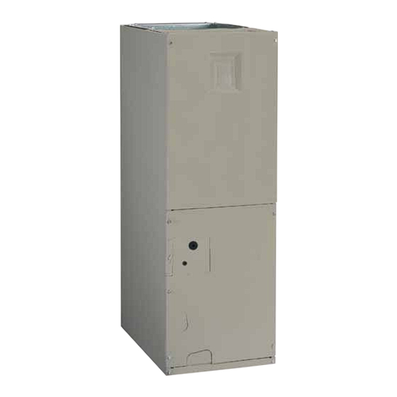
B6BX SERIES AIR HANDLER
INSTALLATION INSTRUCTIONS
IMPORTANT
Please read all information in this manual thoroughly and become familiar with the capabilities
and use of your appliance before attempting to operate or maintain this unit. These instructions
are primarily intended to assist qualified individuals experienced in the proper installation of
this appliance. Some local codes require licensed installation/service personnel for this type
of equipment. Improper installation, service, adjustment, or maintenance may cause explosion,
fire, electrical shock or other hazardous conditions which may result in personal injury or
property damage.
Unless otherwise noted in these instructions, only factory authorized kits or accessories may
be used with this product. Keep this manual where you have easy access to it in the future. If a
problem occurs, check the instructions and follow recommendations given. If these suggestions
don't eliminate your problem, call your servicing contractor.
DO NOT DESTROY. PLEASE READ CAREFULLY AND
KEEP IN A SAFE PLACE FOR FUTURE REFERENCE.
Advertisement
Table of Contents

Related Manuals for Nortek B6BX Series


Summary of Contents for Nortek B6BX Series
- Page 1 B6BX SERIES AIR HANDLER INSTALLATION INSTRUCTIONS IMPORTANT Please read all information in this manual thoroughly and become familiar with the capabilities and use of your appliance before attempting to operate or maintain this unit. These instructions are primarily intended to assist qualified individuals experienced in the proper installation of this appliance.
-
Page 2: Table Of Contents
TABLE OF CONTENTS Startup & Adjustments ..........13 Before You Start the Unit .........13 Important Safety Information ........3 Refrigerant Charging ..........14 Air Circulation ............14 Requirements & Codes ..........3 Running the Blower Continuously ......14 General Information ...........4 Selecting Continuous Low Spd Fan Operation ..14 Before You Install this Unit .........4 Turning the Blower Off..........14 Locating the Air Handler ..........4... -
Page 3: Important Safety Information
IMPORTANT SAFETY INFORMATION REQUIREMENTS & CODES INSTALLER: Please read all instructions before servicing WARNING: this equipment. Pay attention to all safety warnings and any other special notes highlighted in the manual. Safety This unit must be installed in accordance with markings are used frequently throughout this manual to instructions outlined in this manual during designate a degree or level of seriousness and should not... -
Page 4: General Information
GENERAL INFORMATION Minimum Clearances • This appliance must be installed in accordance with This appliance has been tested for capacity and efficiency clearances listed in Figure 1. The air handler must be in accordance with AHRI 210/240 Standards and will installed with ample clearance for easy access to the air provide many years of safe and dependable comfort, filter, blower assembly, heater assembly and controls. -
Page 5: Installation In A Garage
• Seal all connections and joints with industrial grade track the long-term affects of air handler usage during construction. Proof of this submittal shall be available for sealing tape or liquid sealant. Requirements for sealing the final inspection of the air handler prior to occupancy. ductwork vary from region to region. -
Page 6: Air Handler Installation
AIR HANDLER INSTALLATION Horizontal Installations The B6 Series air handler can be installed horizontally in The B6 Series Air Handler is shipped ready for vertical an attic, basement, crawl space or alcove. It can also be upflow installation and is approved for attic, basement, suspended from a ceiling in a basement or utility room in alcove/closet or crawlspace installation with zero either a right to left airflow or left to right airflow as shown in... -
Page 7: Horizontal Left Installations
overflow. Additionally, it is recommended that an approved Horizontal Right Installations: water level indicator or float switch device be used to 1. Remove the coil access door. Unscrew the line-set tube shut down the unit in the event water is detected in the close-off plate from the front left cabinet rail. -
Page 8: Refrigerant Line Connections
• B6BX series air handlers are charged through service 8. Insert the new orifice into the distributor body, rounded end down. See Figure 8 (page 9). -
Page 9: Connecting The Linsets
Connecting the Linesets IMPORTANT NOTES FOR HORIZONTAL OR DOWNFLOW INSTALLATIONS WITH TXV VALVE: • The sensing bulb must be located flush against the suction line for optimum heat transfer. • Avoid attaching the sensing bulb to the lowest part of the suction line where condensate may accumulate. -
Page 10: Condensate Drainage
• If the air handler is located in or above a living space 8. Wrap the refrigerant lines with pressure sensitive neoprene or other suitable material especially where where damage may result from condensate overflow, the lines enter the opening in the sheet metal. an auxiliary drain pan shall be installed under the unit. -
Page 11: Electrical Connections
• If replacing any of the original wires supplied with the ELECTRICAL CONNECTIONS unit, the replacement wire must be copper wire consisting of the same gauge and temperature rating. WARNING: • Provide power supply for the unit in accordance with the unit wiring diagram, and the unit rating plate. -
Page 12: Control Board
low-voltage wiring between the thermostat, outdoor If a heater kit is installed: unit, and control board. NOTE: When the low voltage The B6BX air handler is shipped from the factory without wires are positioned in this grommet, the grommet will an electric heater kit installed. -
Page 13: Startup & Adjustments
STARTUP & ADJUSTMENTS Thermostat WARNING: NITROGEN HEALTH Handler FLAMMABILITY Conditioner REACTIVITY 0 Minimal Hazard 1 Slight Hazard The evaporator coil is shipped from the factory with a nitrogen charge. Use caution when preparing coils for field connections. If repairs make it necessary for evacuation and charging, it should only be attempted by qualified, Typical Air Conditioner with Standard Air Handler... -
Page 14: Refrigerant Charging
Refrigerant Charging Blower Configurations The system refrigerant charge can be checked and 3-Speed Units adjusted through the service ports provided at the front The blower speed is preset at the factory for operation panel of the outdoor unit. Use only gauge lines which have at the same speed for heating and cooling, by using the a Schrader depression device present to actuate the valve. -
Page 15: Unit Maintenance
UNIT MAINTENANCE CABINET SIZE FILTER SIZE Proper maintenance is most important to achieve the best 30.5 cm x 50.8 cm x 2.5 cm performance from a air handler. Some of the components (12 in. x 20 in. x 1 in.) and their locations are shown in Figure 12 (page 17). -
Page 16: Figures & Tables
FIGURES & TABLES 1.9 (3/4) 1.9 (3/4) 1.9 (3/4) 2.9 (1 1/8) (13) Knockout (typ.) 3.2 (1 1/4) “A” 4.8 (1 7/8) Knockout 4.1 (1 5/8) 3.2 (1 1/4) 4.8 (1 7/8) 2.9 (1 1/8) 8.3 (3 1/4) 6.7 (2 5/8) Knockout (typ.) 4.8 (1 7/8) 2.9 (1 1/8) - Page 17 Circuit Breaker (60A) Heating Element Assembly Transformer Motor Control Board Blower Control Upper Door Wheel Board Assembly Capacitor Motor Mount Kit Blower Housing Blower Coil Motor Assembly Filter Door Horizontal Vertical Drain Pan Drain Pan Filter Tracks Lower Door Assembly Figure 13.
-
Page 18: Airflow Data
AIRFLOW DATA Dry Coil .25 (0.1) .5 (0.2) .76 (0.3) 1.0 (0.4) 1.3 (0.5) 1.5 (0.6) 1.8 (0.7) 2.0 (0.8) 296 (627) 270 (572) 234 (496) 018E-A 348 (737) 321 (680) 293 (620) 247 (523) 215 (456) HIGH 434 (920) 403 (853) 365 (774) 328 (694) -
Page 19: Electrical Data & Diagrams
ELECTRICAL DATA & DIAGRAMS 220 VAC 50Hz, Single Phase 240 VAC 50Hz, Single Phase Aux. Heat Multiple Circuit Multiple Circuit Single Single Installed Circuit Circuit Circuit A Circuit B Circuit C Circuit A Circuit B Circuit C (Nom. KW) MCA MOP MCA MOP MCA MOP None... - Page 20 Control Signal Operation Total KW Board Action & MODE Stage 1 Heat on instantly 5 KW Heat blower on after 3 second delay Stage 1 Heat on instantly 10 KW Heat blower on after 3 second delay (EHEAT) Stage 2 Heat on after 5 seconds delay Heat stages off instantly Blower off after 15 second delay Stage 1 Heat on instantly...
- Page 21 RELAY Figure 14. Wiring Diagram for B6BX Series Air Handler with PSC Motor...
- Page 22 Figure 15. Wiring Diagram for B6BX Series Air Handler with ECM Motor...
-
Page 24: Installation / Performance Checklist
INSTALLATION / PERFORMANCE CHECK LIST ELECTRICAL SYSTEM: ATTENTION INSTALLERS: Electrical connections tight? It is your responsibility to know this product better Line voltage polarity correct? than your customer. This includes being able to install the product according to strict safety guidelines and _______ Supply Voltage: ____________________________ instructing the customer on how to operate and maintain...
Need help?
Do you have a question about the B6BX Series and is the answer not in the manual?
Questions and answers