Table of Contents
Advertisement
Quick Links
UM10772
User Manual BFU5xx series starter kits
Rev. 1 — 21 January 2014
Document information
Info
Content
Keywords
BFU520, BFU530, BFU550, BFU520A, BFU530A, BFU550A, BFU520W
BFU530W, BFU550W, BFU520X, BFU530X, BFU550X, BFU520XR,
BFU530XR, BFU550XR, amplifier, LNA, Wide Band Amplifier, PCB
layout, Assembly drawings
Abstract
Document that describes the PCB's and SW content as delivered in the
BFU5xx series transistor starter kit
User manual
Advertisement
Table of Contents

Related Manuals for NXP Semiconductors BFU520


Summary of Contents for NXP Semiconductors BFU520
- Page 1 User manual Document information Info Content Keywords BFU520, BFU530, BFU550, BFU520A, BFU530A, BFU550A, BFU520W BFU530W, BFU550W, BFU520X, BFU530X, BFU550X, BFU520XR, BFU530XR, BFU550XR, amplifier, LNA, Wide Band Amplifier, PCB layout, Assembly drawings Abstract Document that describes the PCB’s and SW content as delivered in the...
- Page 2 UM10772 NXP Semiconductors How to use BFU5xx starter-kit Revision history Date Description 2014-01-21 First publication Contact information For additional information, please visit: http://www.nxp.com For sales office addresses, please send an email to: salesaddresses@nxp.com UM10772 © NXP B.V. 2014. All rights reserved.
-
Page 3: Introduction
See the overview of available starter kits in the table below. Table 1. Customer evaluation kits Transistor Types Evaluation Kit BFU520, BFU530, BFU550 OM7962, starter kit SOT143 BFU520X, BFU530X, BFU550X OM7963, starter kit SOT143X BFU520XR, BFU530XR, BFU550XR OM7964, starter kit SOT143XR... -
Page 4: Content Of The Starter Kits
UM10772 NXP Semiconductors How to use BFU5xx starter-kit Table 2. Application Notes Transistor Type Application Notes (433MHz LNA; 866MHz LNA) BFU520 AN11427; AN11428 BFU530 AN11429; AN11430 BFU550 AN11431; AN11432 BFU520A AN11377; AN11378 BFU530A AN11379; AN11380 BFU550A AN11381; AN11382 BFU520W AN11421; AN11422 BFU530W AN11423;... -
Page 5: The Starter Kit
UM10772 NXP Semiconductors How to use BFU5xx starter-kit 2.1 The starter kit Fig 1. BFU5xx series starter kit UM10772 All information provided in this document is subject to legal disclaimers. © NXP B.V. 2014. All rights reserved. User manual Rev. 1 — 21 January 2014... -
Page 6: Pcb's Example For Bfu5Xx Series Lna
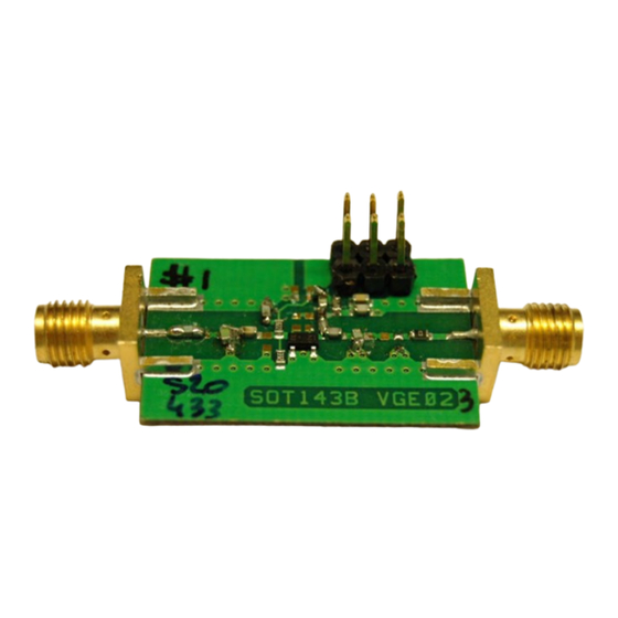
UM10772 NXP Semiconductors How to use BFU5xx starter-kit 2.2 PCB’s example for BFU5xx series LNA Fig 2. PCB’s BFU5-- series populated board, example 433MHz LNA in SOT143 package 3. Target applications for starter kit PCB’s Basically the PCB’s are designed to accommodate an RF amplifier. These could be: 1) LNA’s... -
Page 7: Basic Schematic For Grounded Emitter Versions (Vge0X)
UM10772 NXP Semiconductors How to use BFU5xx starter-kit 3.1 Basic schematic for Grounded Emitter versions (VGE0x) Celectrolytic + Zbias1 Zbias2 Zfb2 Zfb3 RF output Zout1 Zout2 Zout3 RF input Zin1 Zin2 Zin3 Fig 3. Schematic Amplifier design VGE Remarks: Not all components are required, depends on amplifier/matching configuration... -
Page 8: Basic Schematic For Emitter Degeneration Version (Ved0X)
UM10772 NXP Semiconductors How to use BFU5xx starter-kit 3.2 Basic schematic for Emitter Degeneration version (VED0x) Celectrolytic + Zbias1 Zbias2 Zfb2 Zfb3 RF output Zout1 Zout2 Zout3 RF input Zin1 Zin2 Zin3 Fig 4. Schematic Amplifier design VED Remarks: Not all components are required, depends on amplifier/matching configuration... -
Page 9: Pcb Drawings For All Versions
UM10772 NXP Semiconductors How to use BFU5xx starter-kit 4. PCB drawings for all versions On all PCB’s, except SOT143XR types the same circuit can be applied. On all PCB’s except the SOT323, 0603 footprints for capacitors/inductors/resistors are implemented. For SOT323 types this is reduced to 0402 because of the smaller size transistor package. -
Page 10: Sot323 Grounded Emitter
UM10772 NXP Semiconductors How to use BFU5xx starter-kit 4.2 SOT323 Grounded Emitter +Vcc Celectrolytic Zfb2 RF input SMA RF output SMA Zin1 Zin2 Zin3 Zout1 Zout2 Zout3 Fig 6. PCB Assembly drawing Amplifier design VGE Fig 7. PCB Assembly drawing Amplifier design VGE zoomed in UM10772 All information provided in this document is subject to legal disclaimers. -
Page 11: Sot323 Emitter Degeneration
UM10772 NXP Semiconductors How to use BFU5xx starter-kit 4.3 SOT323 Emitter Degeneration +Vcc Celectrolytic Zfb2 RF input SMA RF output SMA Zin1 Zin2 Zin3 Zout1 Zout2 Zout3 Fig 8. PCB Assembly drawing Amplifier design VED Fig 9. PCB Assembly drawing Amplifier design VED zoomed in UM10772 All information provided in this document is subject to legal disclaimers. -
Page 12: Sot23 Grounded Emitter
UM10772 NXP Semiconductors How to use BFU5xx starter-kit 4.4 SOT23 Grounded Emitter +Vcc Celectrolytic Supply Zfb2 RF output SMA RF input SMA Zin1 Zin2 Zin3 Zout3 Zout1 Zout2 Fig 10. PCB Assembly drawing Amplifier design VGE Fig 11. PCB Assembly drawing Amplifier design VGE zoomed in UM10772 All information provided in this document is subject to legal disclaimers. -
Page 13: Sot23 Emitter Degeneration
UM10772 NXP Semiconductors How to use BFU5xx starter-kit 4.5 SOT23 Emitter Degeneration +Vcc Celectrolytic Supply Zfb2 RF input SMA RF output SMA Zin1 Zin2 Zin3 Zout3 Zout1 Zout2 Fig 12. PCB Assembly drawing Amplifier design VED Fig 13. PCB Assembly drawing Amplifier design VED zoomed in UM10772 All information provided in this document is subject to legal disclaimers. -
Page 14: Sot143 Grounded Emitter
UM10772 NXP Semiconductors How to use BFU5xx starter-kit 4.6 SOT143 Grounded Emitter +Vcc Celectrolytic Supply Zfb2 RF input SMA RF output SMA Zin1 Zin2 Zin3 Zout2 Zout3 Zout1 Fig 14. PCB Assembly drawing Amplifier design VGE Fig 15. PCB Assembly drawing Amplifier design VGE zoomed in UM10772 All information provided in this document is subject to legal disclaimers. -
Page 15: Sot143 Emitter Degeneration
UM10772 NXP Semiconductors How to use BFU5xx starter-kit 4.7 SOT143 Emitter Degeneration +Vcc Celectrolytic Supply Zfb2 RF input SMA RF output SMA Zin1 Zin2 Zin3 Zout2 Zout3 Zout1 Fig 16. PCB Assembly drawing Amplifier design VED Fig 17. PCB Assembly drawing Amplifier design VED zoomed in UM10772 All information provided in this document is subject to legal disclaimers. -
Page 16: Sot143X Grounded Emitter
UM10772 NXP Semiconductors How to use BFU5xx starter-kit 4.8 SOT143X Grounded Emitter +Vcc Celectrolytic Supply Zfb2 RF input SMA RF output SMA Zout1 Zout3 Zout2 Zin1 Zin2 Zin3 Fig 18. PCB Assembly drawing Amplifier design VGE Fig 19. PCB Assembly drawing Amplifier design VGE zoomed in UM10772 All information provided in this document is subject to legal disclaimers. -
Page 17: Sot143X Emitter Degeneration
UM10772 NXP Semiconductors How to use BFU5xx starter-kit 4.9 SOT143X Emitter Degeneration +Vcc Celectrolytic Supply Zfb2 RF input SMA RF output SMA Zout1 Zout3 Zout2 Zin1 Zin2 Zin3 Fig 20. PCB Assembly drawing Amplifier design VED Fig 21. PCB Assembly drawing Amplifier design VED zoomed in UM10772 All information provided in this document is subject to legal disclaimers. -
Page 18: Sot143Xr Types, Schematics
UM10772 NXP Semiconductors How to use BFU5xx starter-kit 4.10 SOT143XR types, schematics Celectrolytic + RF output Zfb2 Zfb3 Zout1 Zout2 Zout3 RF input Zin1 Zin2 Zin3 Fig 22. Generic schematic used for SOT143XR Vge types, small differences in DC biasing... -
Page 19: Sot143Xr Grounded Emitter
UM10772 NXP Semiconductors How to use BFU5xx starter-kit 4.11 SOT143XR Grounded Emitter +Vcc Celectrolytic Supply Zfb2 RF input SMA RF output SMA Zout1 Zout2 Zout3 Zin3 Zin1 Zin2 Fig 24. PCB Assembly drawing Amplifier design VGE Fig 25. PCB Assembly drawing Amplifier design VGE zoomed in UM10772 All information provided in this document is subject to legal disclaimers. -
Page 20: Sot143Xr Emitter Degeneration
UM10772 NXP Semiconductors How to use BFU5xx starter-kit 4.12 SOT143XR Emitter Degeneration +Vcc Celectrolytic Supply Zfb2 RF input SMA RF output SMA Zout1 Zout2 Zout3 Zin1 Zin2 Zin3 Fig 26. PCB Assembly drawing Amplifier design VED Fig 27. PCB Assembly drawing Amplifier design VED zoomed in UM10772 All information provided in this document is subject to legal disclaimers. -
Page 21: Usb Memory Device: Content
How to use BFU5xx starter-kit 5. USB memory device: content 5.1 Product Datasheets 15 Datasheets for all BFU520, 530 and 550 types that are commercially available. 5.2 Files for in-circuit Simulations Mextram, Spice, S-parameters 400MHz - 2GHz with Noise, 40MHz - 6GHz no noise, instruction manual for installing the ADS design-kit 5.3 Product Application Notes... -
Page 22: Example Amplifier Designs
UM10772 NXP Semiconductors How to use BFU5xx starter-kit 6. Example amplifier designs Some examples that can be used as starting point, for more detailed description, measurement and simulation results please refer to NXP application notes on BFU5xx series. Basic schematic for Grounded Emitter version (VGE0x) can be found in the next sections. -
Page 23: 866Mhz Lna Using Bfu520A
UM10772 NXP Semiconductors How to use BFU5xx starter-kit 6.2 866MHz LNA using BFU520A Fig 29. 866MHz LNA using BFU520A UM10772 All information provided in this document is subject to legal disclaimers. © NXP B.V. 2014. All rights reserved. User manual Rev. -
Page 24: 433Mhz Lna Using Bfu530A
UM10772 NXP Semiconductors How to use BFU5xx starter-kit 6.3 433MHz LNA using BFU530A Fig 30. 433MHz LNA using BFU530A UM10772 All information provided in this document is subject to legal disclaimers. © NXP B.V. 2014. All rights reserved. User manual Rev. -
Page 25: 866Mhz Lna Using Bfu530A
UM10772 NXP Semiconductors How to use BFU5xx starter-kit 6.4 866MHz LNA using BFU530A Fig 31. 866MHz LNA using BFU530A UM10772 All information provided in this document is subject to legal disclaimers. © NXP B.V. 2014. All rights reserved. User manual Rev. -
Page 26: 433Mhz Lna Using Bfu550W
UM10772 NXP Semiconductors How to use BFU5xx starter-kit 6.5 433MHz LNA using BFU550W Fig 32. 433MHz LNA using BFU550W UM10772 All information provided in this document is subject to legal disclaimers. © NXP B.V. 2014. All rights reserved. User manual Rev. -
Page 27: 866Mhz Lna Using Bfu550W
UM10772 NXP Semiconductors How to use BFU5xx starter-kit 6.6 866MHz LNA using BFU550W Fig 33. 866MHz LNA using BFU550W UM10772 All information provided in this document is subject to legal disclaimers. © NXP B.V. 2014. All rights reserved. User manual Rev. -
Page 28: Legal Information
Notice is herewith given that the subject device uses one or more of the Right to make changes — NXP Semiconductors reserves the right to make following patents and that each of these patents may have corresponding changes to information published in this document, including without patents in other jurisdictions. -
Page 29: Table Of Contents
UM10772 NXP Semiconductors How to use BFU5xx starter-kit 8. Contents Introduction ............3 Content of the starter kits ........4 The starter kit ............. 5 PCB’s example for BFU5xx series LNA ..... 6 Target applications for starter kit PCB’s ... 6 Basic schematic for Grounded Emitter versions (VGE0x) .............
Need help?
Do you have a question about the BFU520 and is the answer not in the manual?
Questions and answers