Table of Contents
Advertisement
Quick Links
Advertisement
Table of Contents

Related Manuals for Asus P8H77-M


Summary of Contents for Asus P8H77-M
- Page 1 P8H77-M...
- Page 2 Product warranty or service will not be extended if: (1) the product is repaired, modified or altered, unless such repair, modification of alteration is authorized in writing by ASUS; or (2) the serial number of the product is defaced or missing.
-
Page 3: Table Of Contents
Contents Safety information ... vii About this guide ... vii P8H77-M specifications summary ... ix Chapter 1 Product introduction Welcome! ... 1-1 Package contents ... 1-1 Special features ... 1-2 1.3.1 Product highlights ... 1-2 1.3.2 DIGI+ VRM Digital Power Desigh ... 1-3 1.3.3... - Page 4 Managing and updating your BIOS ... 2-1 2.1.1 ASUS Update utility ... 2-1 2.1.2 ASUS EZ Flash 2 ... 2-2 2.1.3 ASUS CrashFree BIOS 3 utility ... 2-3 2.1.4 ASUS BIOS Updater ... 2-4 BIOS setup program ... 2-6 Main menu ... 2-10 2.3.1 System Language [English] ...
- Page 5 Contents 2.4.5 DRAM Timing Control ... 2-13 2.4.6 CPU Power Management ... 2-13 2.4.7 DIGI+ VRM ... 2-14 2.4.8 CPU Voltage [Offset Mode] ... 2-16 2.4.9 DRAM Voltage [Auto] ... 2-16 2.4.10 VCCSA Voltage [Auto] ... 2-16 2.4.11 PCH Voltage [Auto] ... 2-16 2.4.12 CPU PLL Voltage [Auto] ...
- Page 6 Contents Tools menu ... 2-27 2.8.1 ASUS EZ Flash 2 Utility ... 2-27 2.8.2 ASUS O.C. Profile ... 2-27 2.8.3 ASUS SPD Information ... 2-27 Exit menu ... 2-28 Appendices Notices ...A-1...
-
Page 7: Electrical Safety
Safety information Electrical safety • To prevent electric shock hazard, disconnect the power cable from the electric outlet before relocating the system. • When adding or removing devices to or from the system, ensure that the power cables for the devices are unplugged before the signal cables are connected. If possible, disconnect all power cables from the existing system before you add a device. -
Page 8: Conventions Used In This Guide
Refer to the following sources for additional information and for product and software updates. ASUS websites The ASUS website provides updated information on ASUS hardware and software products. Refer to the ASUS contact information. Optional documentation Your product package may include optional documentation, such as warranty flyers, that may have been added by your dealer. -
Page 9: P8H77-M Specifications Summary
Intel third generation processors. ® module will run at DDR3 2000/1800 MHz as default. DIMMs of 8GB (or above). ASUS will update QVL once the DIMMs are available on market. Vendors Lists). or more, Windows 32-bit operating system may only ®... - Page 10 Intel H77 Express Chipset: ® - Supports ASUS USB 3.0 Boost UASP Mode* - 2 x USB 3.0/2.0 ports at mid-board for front panel support - 2 x USB 3.0/2.0 ports at back panel (blue) - 10 x USB 2.0/1.1 ports (6 ports at mid-board, 4 ports at back panel) * The USB 3.0 ports only support Windows...
- Page 11 - AI Suite II - ASUS ESD - MemOK! - ASUS Fanless Design: Stylish Heatsink solution - ASUS Fan Xpert - ASUS UEFI BIOS EZ Mode featuring user-friendly interface - ASUS CrashFree BIOS 3 - ASUS EZ Flash 2 - ASUS MyLogo 2...
- Page 12 * Specifications are subject to change without notice. 64 Mb Flash ROM, UEFI BIOS, PnP, DMI v2.0, WfM2.0, SMBIOS v2.6, ACPI v2.0, Multi-language BIOS, ASUS EZ Flash 2, ASUS CrashFree BIOS 3, F12 PrintScreen, F3 Shortcyt Function, and ASUS DRAM SPD (Serial Presence Detect) memory information WfM 2.0, DMI 2.0, WOL by PME, PXE...
-
Page 13: Chapter 1 Product Introduction
® The motherboard delivers a host of new features and latest technologies, making it another standout in the long line of ASUS quality motherboards! Before you start installing the motherboard, and hardware devices on it, check the items in your package with the list below. -
Page 14: Special Features
Special features 1.3.1 Product highlights LGA1155 socket for Intel / Pentium / Celeron ® This motherboard supports Intel processors in the LGA1155 package, with iGPU, memory and PCI Express controllers integrated to support onboard graphics output with dedicated chipsets, 2-channel (4 DIMMs) DDR3 memory and 16 PCI Express 3.0/2.0 lanes. -
Page 15: Digi+ Vrm Digital Power Desigh
Complete USB 3.0 Integration ASUS facilitates the strategic USB 3.0 accessibility for both the front and rear panel – 4 USB 3.0 ports in total. Experience the latest plug & play connectivity at speeds up to 10 times faster than USB 2.0. -
Page 16: Asus Quiet Thermal Solution
ASUS TurboV Easy, Real-Time O.C. Tunings Feel the adrenaline rush of real-time OC-now a reality with the ASUS TurboV. This easy OC tool allows you to overclock without exiting or rebooting the OS; and its user-friendly interface makes overclock with just a few clicks away. Moreover, the ASUS OC profiles in TurboV provides the best O.C. -
Page 17: Asus Ez Diy
ASUS Fan Xpert ASUS Fan Xpert intelligently allows you to adjust the CPU fan speed according to different ambient temperatures caused by different climate conditions in different geographic regions and your PC’s loading. The built-in variety of useful profiles offer flexible controls of fan speed to achieve a quiet and cool environment. - Page 18 The motherboard is European Union’s Energy-related Products (ErP) ready, and ErP requires products to meet certain energy efficiency requirement in regards to energy consumptions. This is in line with ASUS vision of creating environment-friendly and energy-efficient products through product design and innovation to reduce carbon footprint of the product and thus mitigate environmental impacts.
-
Page 19: Before You Proceed
• Before you install or remove any component, ensure that the ATX power supply is switched off or the power cord is detached from the power supply. Failure to do so may cause severe damage to the motherboard, peripherals, or components. ASUS P8H77-M... -
Page 20: Motherboard Overview
Place eight screws into the holes indicated by circles to secure the motherboard to the chassis. Do not overtighten the screws! Doing so can damage the motherboard. Place this side towards the rear of the chassis P8H77-M Chapter 1: Product introduction... -
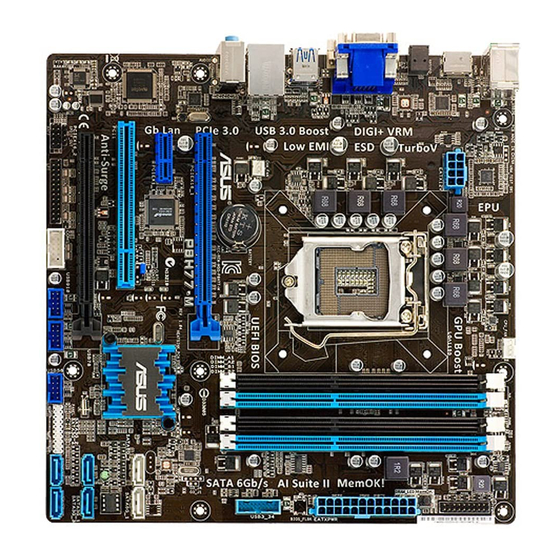
Page 21: Motherboard Layout
CPU socket ® DDR3 DIMM sockets 5. TPM connector (20-1 pin TPM) 6. MemOK! switch DRAM LED 8. USB 3.0 connector (20-1 pin USB3_34) 9. Clear RTC RAM (3-pin CLRTC) ASUS P8H77-M 24.4cm(9.6in) CPU_FAN Lithium Cell CMOS Power PCIEX16_1 P8H77-M 1083... -
Page 22: Central Processing Unit (Cpu)
Contact your retailer immediately if the PnP cap is missing, or if you see any damage to the PnP cap/socket contacts/motherboard components. ASUS will shoulder the cost of repair only if the damage is shipment/transit-related. • Keep the cap after installing the motherboard. ASUS will process Return Merchandise Authorization (RMA) requests only if the motherboard comes with the cap on the LGA1155 socket. -
Page 23: Cpu Installation
1.6.1 CPU installation The LGA1156 CPU is incompatible with the LGA1155 socket. DO NOT install a LGA1156 CPU on the LGA1155 socket. ASUS P8H77-M 1-11... - Page 24 1-12 Chapter 1: Product introduction...
-
Page 25: Cpu Heatsink And Fan Assembly Installation
1.6.2 CPU heatsink and fan assembly installation To install the CPU heatsink and fan assembly ASUS P8H77-M Apply the Thermal Interface Material to the CPU heatsink and CPU before you install the heatsink and fan if necessary. 1-13... - Page 26 To uninstall the CPU heatsink and fan assembly 1-14 Chapter 1: Product introduction...
-
Page 27: System Memory
The figure illustrates the location of the DDR3 DIMM sockets: P8H77-M P8H77-M 240-pin DDR3 DIMM sockets Recommended memory configurations One DIMM: We recommend you install one memory module in either of the blue slots (DIMM_A2 or DIMM_B2) to get better performance. -
Page 28: Memory Configurations
(4 DIMMs) or overclocking condition. • ASUS exclusively provides hyper DIMM support function. • Hyper DIMM support is subject to the physical characteristics of individual CPUs. • Visit the ASUS website at www.asus.com for the latest QVL. 1-16 ®... - Page 29 P8H77-M Motherboard Qualified Vendors List (QVL) DDR3-2400MHz capability Vendors Part No. CORSAIR CMGTX8(XMP) F3-19200CL11Q- G.SKILL 16GBZHD(XMP) G.SKILL F3-19200CL9D-4GBPIS(XMP) GEIL GET34GB2400C9DC(XMP) KINGMAX FLLE88F-C8KKAA HAIS(XMP) Transcend TX2400KLU-4GK(427652)(XMP) 4GB (2x2GB) Transcend TX2400KLU-4GK (381850)(XMP) 4GB (2x2GB) Transcend TX2400KLU-4GK(374243)(XMP) 4GB (2x2GB) PATRIOT PVV34G2400C9K(XMP) DDR3-2250MHz capability Vendors Part No.
- Page 30 DDR3-2000MHz capability Vendors Part No. Apacer 78.AAGD5.9KD(XMP) CORSAIR CMZ4GX3M2A2000C10(XMP) CORSAIR CMT6GX3M3A2000C8(XMP) G.SKILL F3-16000CL9D-4GBFLS(XMP) G.SKILL F3-16000CL9D-4GBTD(XMP) G.SKILL F3-16000CL6T-6GBPIS(XMP) GEIL GUP34GB2000C9DC(XMP) KHX2000C9AD3T1K2/ KINGSTON 4GX(XMP) KHX2000C9AD3W1K2/ KINGSTON 4GX(XMP) KHX2000C9AD3T1K2/ KINGSTON 4GX(XMP) KHX2000C9AD3W1K3/ KINGSTON 6GX(XMP) KHX2000C9AD3T1K3/ KINGSTON 6GX(XMP) Transcend TX2000KLN-8GK(XMP) Asint SLA302G08-ML2HB(XMP) PATRIOT PVT36G2000LLK DDR3-1866MHz capability Vendors Part No.
- Page 31 KINGSTON KHX1600C8D3T1K2/4GX(XMP) 4GB(2 x 2GB) DS KINGSTON KHX1600C9D3K2/4GX(XMP) KINGSTON KHX1600C9D3LK2/4GX(XMP) KINGSTON KHX1600C9D3X2K2/4GX(XMP) 4GB(2 x 2GB) DS KINGSTON KHX1600C9D3T1K3/6GX(XMP) 6GB(3x 2GB ) DS KINGSTON KHX1600C9D3K3/6GX(XMP) KINGSTON KHX1600C9D3T1BK3/ 6GX(XMP) KINGSTON KHX1600C9D3K2/8GX(XMP) ASUS P8H77-M Chip Size Chip NO. Brand 3CCD-1509A A-DATA EL1126T 3GB(3 x 1GB) SS...
- Page 32 DDR3-1600MHz capability Vendors Part No. KINGSTON KHX1600C9D3P1K2/8G Super WA160UX6G9 Talent Transcend JM1600KLN-8GK Asint SLZ3128M8-EGJ1D(XMP) Asint SLA302G08-EGG1C(XMP) Asint SLA302G08-EGJ1C(XMP) Elixir M2P2G64CB8HC9N-DG(XMP) 2GB Kingtiger KTG2G1600PG3 Mushkin 998659(XMP) Mushkin 998659(XMP) PATRIOT PGS34G1600LLKA SanMax SMD-4G68HP-16KZ DDR3-1333MHz capability Vendors Part No. A-DATA AD31333001GOU A-DATA AD3U1333C2G9 A-DATA AD63I1B0823EV A-DATA...
- Page 33 4GB(2 x 2GB) DS - (XMP) KINGSTON KHX1333C9D3UK2/4GX 4GB(2 x 2GB) DS - (XMP) KINGSTON KVR1333D3N9/4G (low profile) KINGSTON KVR1333D3N9/4G (low profile) KINGSTON KVR1333D3N9/4G KINGSTON KVR1333D3N9/4G ASUS P8H77-M Chip Chip NO. Timing Brand SS ELPIDA J1108EDSE-DJ-F DS ELPIDA J1108EDSE-DJ-F SS G.SKILL 9-9-9-24 7-7-7-18 8-8-8-8-24 XMP 1.35V...
- Page 34 DDR3-1333MHz capability Vendors Part No. KVR1333D3N9/4G-SP KINGSTON (low profile) Micron MT4JTF12864AZ-1G4D1 Micron MT8JTF12864AZ-1G4F1 Micron MT8JTF25664AZ-1G4D1 Micron MT8JTF25664AZ-1G4M1 Micron MT16JTF25664AZ-1G4F1 2GB Micron MT16JTF51264AZ-1G4D1 4GB NANYA NT4GC64B8HG0NF-CG AL7F8G73F-DJ2 AL8F8G73F-DJ2 SAMSUNG M378B2873FHS-CH9 SAMSUNG M378B5773DH0-CH9 SAMSUNG M378B5673FH0-CH9 SAMSUNG M378B5273CH0-CH9 SAMSUNG M378B1G73AH0-CH9 Super Talent W1333UA1GH Super Talent W1333UX2G8(XMP) Super Talent...
- Page 35 We suggest that you install the modules into slots A2 and B2 for better compatibility. • 4 DIMMs*: four (4) modules inserted into both the blue slots and the black slots as two pairs of dual-channel memory configuration. ASUS P8H77-M Chip Chip NO. Timing Voltage...
-
Page 36: Installing A Dimm
1.7.3 Installing a DIMM To remove a DIMM 1-24 Chapter 1: Product introduction... -
Page 37: Expansion Slots
This motherboard supports PCI Express 2.0 x1 network cards, SCSI cards, and other cards that comply with the PCI Express specifications. 1.8.5 PCI Express 2.0 x16 slots This motherboard has two PCI Express 2.0 x16 slots that support PCI Express x16 2.0 graphic cards complying with the PCI Express specifications. ASUS P8H77-M 1-25... -
Page 38: Pci Express 3.0 X16 Slot
1.8.6 PCI Express 3.0 x16 slot This motherboard has one PCE Express 3.0 x 16 slot that supports PCI Express 3.0 x 16 graphics cards complying with the PCI Express specifications. VGA configuration Single VGA/PCIe card Dual VGA/PCIe card • PCIe 3.0 support depends on CPU type and requires PCIe 3.0 VGA card. •... -
Page 39: Jumpers
CMOS RTC RAM data. The onboard button cell battery powers the RAM data in CMOS, which include system setup information such as system passwords. P8H77-M P8H77-M Clear RTC RAM To erase the RTC RAM: 1. Turn OFF the computer and unplug the power cord. -
Page 40: Connectors
1.10 Connectors 1.10.1 Rear panel connectors PS/2 Keyboard/Mouse COMBO port. This port is for a PS/2 keyboard/mouse. Video Graphics Adapter (VGA) port. This 15-pin port is for a VGA monitor or other VGA-compatible devices. LAN (RJ-45) port. This port allows Gigabit connection to a Local Area Network (LAN) through a network hub. -
Page 41: Internal Connectors
I/O module cable to this connector. P8H77-M P8H77-M Front panel audio connector If you want to connect a high-definition front panel audio module to this connector, ensure that the Front Panel Type item in the BIOS is set to [HD Audio]. If you want to connect an AC97 front panel audio module to this connector, set the item to [AC97]. - Page 42 Intel chipset. P8H77-M P8H77-M Intel ® • These connectors are set to [AHCI] by default. If you intend to create a Serial ATA RAID set using these connectors, set the SATA Mode Selection item in the BIOS to [RAID].
- Page 43 If you installed Serial ATA hard disk drives, you can create a RAID 0, 1, 5, and 10 configuration with the Intel chipset. P8H77-M P8H77-M Intel SATA 3.0Gb/s connectors ® • These connectors are set to [AHCI] by default. If you intend to create a Serial ATA RAID set using these connectors, set the SATA Mode Selection item in the BIOS to [RAID].
-
Page 44: Usb 2.0 Connectors
USB 3.0 connector, you can have a front panel USB 3.0 solution. P8H77-M P8H77-M USB3.0 Front panel connector The USB 3.0 module is purchased separately. USB 2.0 connectors (10-1 pin USB56, USB78, USB910) These connectors are for USB 2.0 ports. - Page 45 This connector is for a serial (COM) port. Connect the serial port module cable to this connector, then install the module to a slot opening at the back of the system chassis. P8H77-M P8H77-M Serial port (COM1) connector The COM module is purchased separately. ASUS P8H77-M...
- Page 46 • The CPU_FAN connector supports the CPU fan of maximum 1A (12 W) fan power. • Only the CPU_FAN connector supports the ASUS FAN Xpert feature. • If you install two VGA cards, we recommend that you plug the rear chassis fan cable to the motherboard connector labeled CHA_FAN for better thermal environment.
- Page 47 • If you want to use two high-end PCI Express x16 cards, use a PSU with 1000W power or above to ensure the system stability. • If you are uncertain about the minimum power supply requirement for your system, refer to the Recommended Power Supply Wattage Calculator at http://support.asus. com/PowerSupplyCalculator/PSCalculator.aspx?SLanguage=en-us for details. ASUS P8H77-M...
-
Page 48: System Panel Connector
System panel connector (20-8 pin PANEL) This connector supports several chassis-mounted functions. P8H77-M P8H77-M System panel connector • System power LED (2-pin PLED) This 2-pin connector is for the system power LED. Connect the chassis power LED cable to this connector. The system power LED lights up when you turn on the system power, and blinks when the system is in sleep mode. - Page 49 IEEE 1284, which is the parallel port interface on IBM PC-compatible computers. P8H77-M P8H77-M Parallel Port Connector TPM connector (20-1 pin TPM) This connector supports a Trusted Platform Module (TPM) system, which can securely store keys, digital certificates, passwords, and data. A TPM system also helps enhance network security, protects digital identities, and ensures platform integrity.
-
Page 50: Onboard Switches
If the installed DIMMs still fail to boot after the whole tuning process, the DRAM_LED lights continuously. Replace the DIMMs with ones recommended in the Memory QVL (Qualified Vendors Lists) in this user manual or on the ASUS website at www.asus.com. -
Page 51: Onboard Leds
The illustration below shows the location of the onboard LED. P8H77-M P8H77-M Onboard LED DRAM LED DRAM LED checks the DRAM in sequence during motherboard booting process. If an error is found , the LED next to the error device will continue lighting until the problem is solved. -
Page 52: Software Support
The contents of the Support DVD are subject to change at any time without notice. Visit the ASUS website at www.asus.com for updates. To run the Support DVD Place the Support DVD to the optical drive. -
Page 53: Introduction To Intel® 2012 Desktop Responsiveness Technologies
5. DRAM: To enable Intel® Rapid Start Technology, DRAM size smaller than 8GB is required. Ensure to enable the acceleration of Intel creating the partition for the Intel ASUS P8H77-M 2012 Desktop responsiveness, you must ® Smart Response Technology before ®... - Page 54 SSD Capacity Requirements SSD Partition Capacity Requirements Intel Rapid Start ® Intel Smart Response ® Intel Smart Response ® Intel Rapid Start ® Intel Smart Response, ® Intel Rapid Start, ® Intel Smart Connect ® • The SSD used for Intel creating RAID.
-
Page 55: Intel ® Smart Response Technology
THROUGH, write to SSD and HDD at the same time. Maximized mode: WRITE BACK, write to SSD and write back to HDD in a later time. ASUS P8H77-M ® Smart Response Technology, setting the SATA Mode BIOS item to Rapid Storage Technology Driver software. ®... -
Page 56: Intel ® Rapid Start Technology
Select Disable Acceleration to disable this function, and select Change Mode to switch acceleration mode to Enhanced/ Maximized. • To enable Intel a HDD, and only one SSD can be assigned for caching. • If you want to restore the OS, go to BIOS Option ROM > Acceleration Options and remove the Disks/Volume Acceleration to disable Intel Refer to Chapter 4, section Installing Serial ATA hard disk for the entry of BIOS Option ROM. - Page 57 Go to Start > Control Panel > System and Security > System, and check the DRAM size information. The unallocated volume is allocated to the selected disk. ASUS P8H77-M Smart Response to allow enough capacity for the ® ® 1-45...
- Page 58 To launch the disk partitioning tool, click Start > Programs > Accessories > Command Prompt tool. Type diskpart and press Enter. In the diskpart prompt, type list disk after DISKPART, and press Enter. Select the disk with the unallocated volume by typing select disk x (x = disk number), and press Enter.
- Page 59 Rapid Start Technology. ® Click the Show hidden icons arrow from the right side of the task bar, and click Intel Manager icon. ASUS P8H77-M Rapid Start Technology is incomplete if the computer is not rebooted, ® Rapid Start Technology. ®...
-
Page 60: Recovering The Partition
Tick On in the Status field to enable the function, and click Save. Click to enable or disable battery saving mode. This function only applies to notebooks. Click to enable or disable the timer. When enabled, move the scroll bar to the desired time. When the system is idle for more than the time period you set, the system automatically goes into the Intel mode. - Page 61 In the desktop, click Start, right-click Computer, and click Manage. In the Computer Management window, click Disk Management, right click the shrinked new volume, and select Extend Volume. As the Extend Volume Wizard appears, click Next. ASUS P8H77-M ® 1-49...
-
Page 62: Intel ® Smart Connect Technology
Click Next after selecting the default selected disk. Extend volume setup is completed. Click Finish to recover the Intel Technology partition. Reboot the system after deleting the partition. Go to Start > Control Panel > Programs > Programs and Features > to remove the Intel Rapid Start Manager for the complete deletion of Intel ®... -
Page 63: Intel ® Smart Connect Technology
Click to enable or disable the function When the scroll bar is activated, adjust the waking up time period for Internet data update. ASUS P8H77-M Smart Connect ® Smart Connect ® Smart Connect Technology. ® Click to view version information... - Page 64 To disable the updating function, click Disable Updating. Clicking this button automatically disables the configuration in the Advanced tab. To reset to defaults, click Reset All to Defaults. In the Advanced tab, set up the schedule during low power usage time period for power saving.
-
Page 65: Chapter 2 Bios Information
Updating the BIOS To update the BIOS: From the Windows desktop, click Start > Programs > ASUS > AI Suite II > AI Suite II X.XX.XX to ® launch the AI Suite II utility. The AI Suite II Quick Bar appears. -
Page 66: Asus Ez Flash 2
Insert the USB flash disk that contains the latest BIOS file to the USB port. Enter the Advanced Mode of the BIOS setup program. Go to the Tool menu to select ASUS EZ Flash 2 Utility and press <Enter> to enable it. -
Page 67: Asus Crashfree Bios 3 Utility
2.1.3 ASUS CrashFree BIOS 3 utility The ASUS CrashFree BIOS 3 is an auto recovery tool that allows you to restore the BIOS file when it fails or gets corrupted during the updating process. You can restore a corrupted BIOS file using the motherboard support DVD or a USB flash drive that contains the updated BIOS file. -
Page 68: Asus Bios Updater
Insert the USB flash drive with the latest BIOS file and BIOS Updater to the USB port. Boot your computer. When the ASUS Logo appears, press <F8> to show the BIOS Boot Device Select Menu. Insert the support DVD into the optical drive and select the optical drive as the boot device. -
Page 69: Updating The Bios File
Select the Load Optimized Defaults item under the Exit menu. Refer to section 2.9 Exit menu for details. • Ensure to connect all SATA hard disk drives after updating the BIOS file if you have disconnected them. ASUS P8H77-M Update ROM... -
Page 70: Bios Setup Program
• The BIOS setup screens shown in this section are for reference purposes only, and may not exactly match what you see on your screen. • Visit the ASUS website at www.asus.com to download the latest BIOS file for this motherboard. - Page 71 • The boot device options vary depending on the devices you installed to the system. • The Boot Menu(F8) button is available only when the boot device is installed to the system. ASUS P8H77-M Selects the display language of the BIOS setup program...
-
Page 72: Advanced Mode
The Advanced Mode provides advanced options for experienced end-users to configure the BIOS settings. The figure below shows an example of the Advanced Mode. Refer to the following sections for the detailed configurations. To access the EZ Mode, click Exit, then select ASUS EZ Mode. Back button Menu items... -
Page 73: Configuration Fields
You cannot select an item that is not user-configurable. A configurable field is highlighted when selected. To change the value of a field, select it and press <Enter> to display a list of options. ASUS P8H77-M... -
Page 74: Main Menu
Main menu The Main menu screen appears when you enter the Advanced Mode of the BIOS Setup program. The Main menu provides you an overview of the basic system information, and allows you to set the system date, time, language, and security settings. 2.3.1 System Language [English] Allows you to choose the BIOS language version from the options. -
Page 75: Administrator Password
To clear the user password, follow the same steps as in changing a user password, but press <Enter> when prompted to create/confirm the password. After you clear the password, the User Password item on top of the screen shows Not Installed. ASUS P8H77-M 2-11... -
Page 76: Ai Tweaker Menu
Ai Tweaker menu The Ai Tweaker menu items allow you to configure overclocking-related items. Be cautious when changing the settings of the Ai Tweaker menu items. Incorrect field values can cause the system to malfunction. The configuration options for this section vary depending on the CPU and DIMM model you installed on the motherboard. -
Page 77: Ai Overclock Tuner [Auto]
The sub-items in this menu allow you to set the CPU ratio and features. CPU Ratio [Auto] Allows you to manually adjust the maximum non-turbo CPU ratio. Use <+> and <-> keys or the numeric keypad to adjust the value. The valid value ranges vary according to your CPU model. ASUS P8H77-M 2-13... -
Page 78: Digi+ Vrm
Enhanced Intel SpeedStep Technology [Enabled] Allows you to enable or disable the Enhanced Intel [Disabled] Disables this function. [Enabled] The operating system dynamically adjusts the processor voltage and core frequency which may result in decreased average consumption and decreased average heat production. Turbo Mode [Enabled] This item appears only when you set the previous item to [Enabled]. - Page 79 100% (Extreme). Configuration options: [Auto] [Regular] [High] [Extreme] iGPU Current Capability [100%] Allows you to set the iGPU Current Capability. Configuration options: [100%] [110%] [120%] Do not remove the thermal module while changing the DIGI+ VRM related parrameters. The thermal conditions should be monitored. ASUS P8H77-M 2-15...
-
Page 80: Cpu Voltage [Offset Mode]
Some of the following items are adjusted by typing the desired values using the numeric keypad and press the <Enter> key. You can also use the <+> and <-> keys to adjust the value. To restore the default setting, type [auto] using the keyboard and press the <Enter> key. -
Page 81: Advanced Menu
Allows legacy operating systems to boot even without support for CPUs with extended CPUID functions. [Disabled] Disables this function. Execute Disable Bit [Enabled] [Enabled] Enables the No-Execution Page Protection Technology. [Disabled] Forces the XD feature flag to always return to zero (0). ASUS P8H77-M 2-17... -
Page 82: Pch Configuration
Intel Virtualization Technology [Disabled] ® [Enabled] Allows a hardware platform to run multiple operating systems separately and simultaneously, enabling one system to virtually function as several systems. [Disabled] Disables this function. Hardware Prefetcher [Enabled] [Enabled] Allows a hardware platform to run multiple operating systems separately and simultaneously, enabling one system to virtually function as several systems. -
Page 83: Sata Configuration
Allows you to select the amount of system memory allocated to DVMT 5.0 used by the iGPU. Configuration options: [32M] [64M] [96M] [128M] ~ [416M] [448M] [480M] [512M] Render Standby [Enabled] Allows you to enable the Intel Graphics Render Standby support to reduce the iGPU power use when idle. Configuration options: [Disabled] [Enabled] ASUS P8H77-M 2-19... -
Page 84: Usb Configuration
iGPU Multi-Monitor [Enabled] Allows you to enable the iGPU Multi-Monitor. For Lucid Virtu MVP function support, set this item to [Enabled] to empower both integrated and discrete graphics. iGPU shared system memory size is fixed in 64MB. Configuration options: [Disabled] [Enabled] NB PCIe Configuration Allows you to configure the NB PCI Express settings. -
Page 85: Parallel Port Configuration
Device Mode [STD Printer Mode] Allows you to change the printer port mode. Configuration options: [STD Printer Mode] [SPP Mode] [EPP-1.9 and SPP Mode] [EPP-1.7 and SPP Mode] [ECP Mode] [ECP and EPP 1.9 Mode] [ECP and EPP 1.7 Mode] ASUS P8H77-M 2-21... -
Page 86: Apm
2.5.7 Restore AC Power Loss [Power Off] [Power On] The system goes into on state after an AC power loss. [Power Off] The system goes into off state after an AC power loss. [Last State] The system goes into either off or on state, whatever the system state was before the AC power loss. -
Page 87: Monitor Menu
N/A. Select Ignore if you do not wish to display the detected speed. 2.6.3 CPU Voltage, 3.3V Voltage, 5V Voltage, 12V Voltage The onboard hardware monitor automatically detects the voltage output through the onboard voltage regulators. Select Ignore if you do not want to detect this item. ASUS P8H77-M 2-23... -
Page 88: Cpu Q-Fan Control [Enabled]
2.6.4 CPU Q-Fan Control [Enabled] [Disabled] Disables the CPU Q-Fan control feature. [Enabled] Enables the CPU Q-Fan control feature. CPU Fan Speed Low Limit [200 RPM] This item appears only when you enable the CPU Q-Fan Control feature and allows you to disable or set the CPU fan warning speed. -
Page 89: Boot Menu
[Disabled] Disables the full screen logo display feature. Set this item to [Enabled] to use the ASUS MyLogo 2™ feature. Post Report [5 sec] This item appears only when the Full Screen Logo item is set to [Disabled] and allows you to set the waiting time for the system to display the post report. -
Page 90: Option Rom Messages [Force Bios]
• To select the boot device during system startup, press <F8> when ASUS Logo appears. • To access Windows OS in Safe Mode, press <F8> after POST. -
Page 91: Tools Menu
<Enter> to display the submenu. 2.8.1 ASUS EZ Flash 2 Utility Allows you to run ASUS EZ Flash 2. Press [Enter] to launch the ASUS EZ Flash 2 screen. For more details, see section 2.1.2 ASUS EZ Flash 2. 2.8.2 ASUS O.C. -
Page 92: Exit Menu
This option allows you to exit the Setup program without saving your changes. When you select this option or if you press <Esc>, a confirmation window appears. Select Yes to discard changes and exit. ASUS EZ Mode This option allows you to enter the EZ Mode screen. Launch EFI Shell from filesystem device This option allows you to attempt to launch the EFI Shell application (shellx64.efi) from one of... -
Page 93: Appendices
Cet appareil est conforme aux normes CNR exemptes de licence d’Industrie Canada. Le fonctionnement est soumis aux deux conditions suivantes : (1) cet appareil ne doit pas provoquer d’interférences et (2) cet appareil doit accepter toute interférence, y compris celles susceptibles de provoquer un fonctionnement non souhaité de l’appareil. ASUS P8H77-M... -
Page 94: Canadian Department Of Communications Statement
ASUS Recycling/Takeback Services ASUS recycling and takeback programs come from our commitment to the highest standards for protecting our environment. We believe in providing solutions for you to be able to responsibly recycle our products, batteries, other components as well as the packaging materials. Please go to http://csr.asus.com/english/Takeback.htm for the detailed recycling information in different... -
Page 95: Asus Contact Information
Online support ASUS COMPUTER INTERNATIONAL (America) Address Telephone Web site Technical Support Telephone Support fax Online support ASUS COMPUTER GmbH (Germany and Austria) Address Web site Online contact Technical Support Telephone (Component) Telephone (System/Notebook/Eee/LCD) Support Fax Online support * EUR 0.14/minute from a German fixed landline; EUR 0.42/minute from a mobile phone.
Need help?
Do you have a question about the P8H77-M and is the answer not in the manual?
Questions and answers