Table of Contents
Advertisement
Advertisement
Table of Contents

Related Manuals for Asus P8H77-I


Summary of Contents for Asus P8H77-I
- Page 1 P8H77-I...
- Page 2 Product warranty or service will not be extended if: (1) the product is repaired, modified or altered, unless such repair, modification of alteration is authorized in writing by ASUS; or (2) the serial number of the product is defaced or missing.
-
Page 3: Table Of Contents
Contents Safety information ... vi About this guide ... vii P8H77-I specifications summary ... ix Chapter 1 Product introduction Welcome! ... 1-1 Package contents ... 1-1 Special features ... 1-1 1.3.1 Product highlights ... 1-1 1.3.2 Innovative ASUS features ... 1-3 Before you proceed ... - Page 4 Managing and updating your BIOS ... 2-1 2.1.1 ASUS Update utility ... 2-1 2.1.2 ASUS EZ Flash 2 ... 2-2 2.1.3 ASUS CrashFree BIOS 3 utility ... 2-3 2.1.4 ASUS BIOS Updater ... 2-4 BIOS setup program ... 2-7 Main menu ... 2-11 2.3.1 System Language [English] ...2-11...
- Page 5 UEFI/Legacy Boot [Enabled both UEFI and Legacy] ... 2-26 2.7.7 Boot Option Priorities ... 2-26 2.7.8 Boot Override ... 2-26 Tools menu ... 2-27 2.8.1 ASUS EZ Flash 2 Utility ... 2-27 2.8.2 ASUS O.C. Profile ... 2-27 2.8.3 ASUS SPD Information ... 2-27 Exit menu ... 2-28...
-
Page 6: Electrical Safety
Safety information Electrical safety • To prevent electric shock hazard, disconnect the power cable from the electric outlet before relocating the system. • When adding or removing devices to or from the system, ensure that the power cables for the devices are unplugged before the signal cables are connected. If possible, disconnect all power cables from the existing system before you add a device. -
Page 7: About This Guide
Refer to the following sources for additional information and for product and software updates. ASUS websites The ASUS website provides updated information on ASUS hardware and software products. Refer to the ASUS contact information. Optional documentation Your product package may include optional documentation, such as warranty flyers, that may have been added by your dealer. -
Page 8: Conventions Used In This Guide
Conventions used in this guide To ensure that you perform certain tasks properly, take note of the following symbols used throughout this manual. DANGER/WARNING: Information to prevent injury to yourself when trying to complete a task. CAUTION: Information to prevent damage to the components when trying to complete a task. -
Page 9: P8H77-I Specifications Summary
DDR3 1600 MHz and above memory frequency is supported by Intel ** The maximum 16GB memory capacity can be supported with 8GB or above DIMMs. ASUS will update the memory QVL once the DIMMs are available in the market. *** Refer to www.asus.com for the latest Memory QVL (Qualified Vendors List). - Page 10 P8H77-I specifications summary Internal I/O Connector BIOS Manageability Accessories Support DVD Form Factor * Specifications are subject to change without notice. 1 x USB 2.0 connectors support additional 2 USB 2.0 ports 1 x USB 3.0 connectors support additional 2 USB 3.0 ports...
-
Page 11: Chapter 1 Product Introduction
® The motherboard delivers a host of new features and latest technologies, making it another standout in the long line of ASUS quality motherboards! Before you start installing the motherboard, and hardware devices on it, check the items in your package with the list below. -
Page 12: Intel ® H77 Express Chipset
Complete USB 3.0 Integration ASUS facilitates strategic USB 3.0 accessibility for both the front and rear panel – 4 USB 3.0 ports in total. Experience the latest plug & play connectivity at speeds up to 10 times faster than USB 2.0. This motherboard affords greater convenience to high speed connectivity. -
Page 13: Innovative Asus Features
BIOS file using the bundled support DVD or USB flash disk that contains the latest BIOS file. ASUS EZ Flash 2 ASUS EZ Flash 2 is a utility that allows you to update the BIOS without using an OS-based utility. ASUS P8H77-I... -
Page 14: Usb 3.0 Boost
ASUS Fan Xpert ASUS Fan Xpert intelligently allows you to adjust the CPU and chassis fan speeds according to different ambient temperatures caused by different climate conditions in different geographic regions and your PC’s loading. -
Page 15: Lucidlogix Virtu Mvp
ErP requires products to meet certain energy efficiency requirements in regards to energy consumptions. This is in line with ASUS vision of creating environment-friendly and energy-efficient products through product design and innovation to reduce carbon footprint of the product and thus mitigate environmental impacts. -
Page 16: Onboard Led
ON, in sleep mode, or in soft-off mode. This is a reminder that you should shut down the system and unplug the power cable before removing or plugging in any motherboard component. The illustration below shows the location of the onboard LED. P8H77-I Onboard LED SB_PWR Standby Power... -
Page 17: Motherboard Overview
Screw holes Place four screws into the holes indicated by circles to secure the motherboard to the chassis. Do not overtighten the screws! Doing so can damage the motherboard. Place this side towards the rear of the chassis ASUS P8H77-I... -
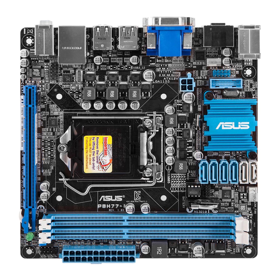
Page 18: Motherboard Layout
1.5.3 Motherboard layout KBMS_USB56 CPU_FAN HDMI SPDIFO 1442 USB3_12 USB34 LAN_USB12 AUDIO AAFP VT1708S 1.5.4 Layout contents Connectors/Jumpers/Slots/LED CPU, chassis fan connectors (4-pin CPU_FAN, 4-pin CHA_FAN) USB connectors (10-1 pin USB78) USB 3.0 connector (20-1 pin USB3_34) ATX power connectors (24-pin EATXPWR, 4-pin EATX12V) Intel LGA1155 CPU socket... -
Page 19: Central Processing Unit (Cpu)
Contact your retailer immediately if the PnP cap is missing, or if you see any damage to the PnP cap/socket contacts/motherboard components. ASUS will shoulder the cost of repair only if the damage is shipment/transit-related. • Keep the cap after installing the motherboard. ASUS will process Return Merchandise Authorization (RMA) requests only if the motherboard comes with the cap on the LGA1155 socket. - Page 20 Lift the load lever in the direction of the arrow until the load plate is completely lifted. Position the CPU over the socket, ensuring that the gold triangle is on the bottom-left corner of the socket, and then fit the socket alignment keys into the CPU notches.
- Page 21 If so, skip this step. The Thermal Interface Material is toxic and inedible. DO NOT eat it. If it gets into your eyes or touches your skin, wash it off immediately, and seek professional medical help. ASUS P8H77-I PnP cap 1-11...
-
Page 22: Installing The Cpu Heatsink And Fan
1.6.2 Installing the CPU heatsink and fan The Intel LGA1155 processor requires a specially designed heatsink and fan assembly to ® ensure optimum thermal condition and performance. • When you buy a boxed Intel heatsink assembly. If you buy a CPU separately, ensure that you use only Intel multi-directional heatsink and fan. -
Page 23: Uninstalling The Cpu Heatsink And Fan
Disconnect the CPU fan cable from the connector on the motherboard. Rotate each fastener counterclockwise. Pull up two fasteners at a time in a diagonal sequence to disengage the heatsink and fan assembly from the motherboard. ASUS P8H77-I CPU FAN PWM CPU FAN IN CPU FAN PWR... -
Page 24: System Memory
A DDR3 module has the same physical dimensions as a DDR2 DIMM but is notched differently to prevent installation on a DDR2 DIMM socket. DDR3 modules are developed for better performance with less power consumption. The figure illustrates the location of the DDR3 DIMM sockets: P8H77-I 240-pin DDR3 DIMM sockets 1-14 Channel Sockets... -
Page 25: Memory Configurations
• The maximum 32GB memory capacity can be supported with 8GB or above DIMMs. ASUS will update the memory QVL once the DIMMs are available in the market. • The default memory operation frequency is dependent on its Serial Presence Detect (SPD), which is the standard way of accessing information from a memory module. - Page 26 DDR3-2200 MHz capability Vendors Part No. GEIL GET34GB2200C9DC(XMP) GEIL GET38GB2200C9ADC(XMP) KINGMAX FLKE85F-B8KJAA-FEIS(XMP) KINGMAX FLKE85F-B8KHA EEIH(XMP) KINGMAX FLKE85F-B8KJA FEIH(XMP) DDR3-2133 MHz capability Vendors Part No. A-DATA AX3U2133GC2G9B-DG2(XMP) CORSAIR CMT16GX3M4X2133C9(XMP 1.3) CORSAIR CMT4GX3M2A2133C9(XMP) CORSAIR CMT4GX3M2B2133C9(XMP) CORSAIR CMT8GX3M2B2133C9(XMP) G.SKILL F3-17000CL9Q-16GBZH(XMP1.3) GEIL GE34GB2133C9DC(XMP) GEIL GU34GB2133C9DC(XMP) KINGSTON KHX2133C9AD3T1K2/4GX(XMP) KINGSTON KHX2133C9AD3X2K2/4GX(XMP)
- Page 27 4GX(XMP) KHX1600C9D3T1K3/ KINGSTON 6GX(XMP) KINGSTON KHX1600C9D3K3/6GX(XMP) KHX1600C9D3T1BK3/ KINGSTON 6GX(XMP) KINGSTON KHX1600C9D3K2/8GX(XMP) KINGSTON KHX1600C9D3P1K2/8G Super Talent WA160UX6G9 Transcend JM1600KLN-8GK ASUS P8H77-I Chip Size Chip NO. Brand 3CCD-1509A A-DATA EL1126T 3GB(3 x 1GB) SS 4GB(2 x 2GB) DS 3CCD-1509 A-DATA A EL1126T...
- Page 28 DDR3-1600 MHz capability Vendors Part No. A-DATA AM2U16BC2P1 A-DATA AD31600E001GM(O)U3K A-DATA AX3U1600XB2G79-2X(XMP) A-DATA AM2U16BC4P2 A-DATA AX3U1600GC4G9-2G(XMP) A-DATA AX3U1600XC4G79-2X(XMP) CORSAIR TR3X3G1600C8D(XMP) CORSAIR CMD12GX3M6A1600C8(XMP) 12GB(6x2GB) DS CORSAIR CMP4GX3M2A1600C8(XMP) DDR3-1333 MHz capability Vendors Part No. A-DATA AD31333001GOU A-DATA AD3U1333C2G9 A-DATA AD63I1B0823EV A-DATA AM2U139C2P1 A-DATA AX3U1333C2G9-BP A-DATA...
- Page 29 Super Talent W1333UB2GS Super Talent W1333UB4GS Super Talent W1333UX6GM Transcend JM1333KLN-2G Transcend TS256MLK64V3U PC3-10600 DDR3 Century -1333 9-9-9 ASUS P8H77-I Size Chip Brand Chip NO. 4GB(2 GEIL GL1L128M88BA12N x 2GB) 4GB(2 x 2GB) DS 4GB(2 x 2GB) DS Hynix H5TC1G83TFRH9A...
- Page 30 • 2 DIMMs Supports one pair of modules inserted into both the blue slot and the black slot as one pair of dual-channel memory configuration. • DDR3 1600 MHz and above memory frequency is supported by Intel processors. • Visit the ASUS website at www.asus.com for the latest QVL. 1-20 Size Chip Brand Chip NO.
-
Page 31: Installing A Dimm
Support the DIMM lightly with your fingers when pressing the retaining clips. The DIMM might get damaged when it flips out with extra force. Remove the DIMM from the socket. ASUS P8H77-I DIMM notch Unlocked retaining clip DIMM slot key... -
Page 32: Expansion Slots
Expansion slots In the future, you may need to install expansion cards. The following sub-sections describe the slots and the expansion cards that they support. Unplug the power cord before adding or removing expansion cards. Failure to do so may cause you physical injury and damage motherboard components. -
Page 33: Clear Rtc Ram (3-Pin Clrtc)
CMOS RTC RAM data. The onboard button cell battery powers the RAM data in CMOS, which include system setup information such as system passwords. P8H77-I Clear RTC RAM To erase the RTC RAM: 1. Turn OFF the computer and unplug the power cord. -
Page 34: Connectors
1.10 Connectors 1.10.1 Rear panel connectors PS/2 Keyboard / Mouse combo port. This port is for a PS/2 keyboard or mouse. Optical S/PDIF Out port. This port connects an external audio output device via an optical S/PDIF cable. Video Graphics Adapter (VGA) port. This 15-pin port is for a VGA monitor or other VGA-compatible devices. - Page 35 HDCP compliant allowing playback of HD DVD, Blu-ray, and other protected content. USB 2.0 ports 5 and 6. These two 4-pin Universal Serial Bus (USB) ports are available for connecting USB 2.0 devices. ASUS P8H77-I ® ® 1-25...
-
Page 36: Internal Connectors
HD Audio or legacy AC`97 audio standard. Connect one end of the front panel audio I/O module cable to this connector. P8H77-I Front panel audio connector • We recommend that you connect a high-definition front panel audio module to this connector to avail of the motherboard’s high-definition audio capability. - Page 37 • If you are uncertain about the minimum power supply requirement for your system, refer to the Recommended Power Supply Wattage Calculator at http://support.asus. com/PowerSupplyCalculator/PSCalculator.aspx?SLanguage=en-us for details. CPU, and chassis fan connectors (4-pin CPU_FAN, 4-pin CHA_FAN) Connect the fan cables to the fan connectors on the motherboard, ensuring that the black wire of each cable matches the ground pin of the connector.
-
Page 38: System Panel Connector
Speaker connector (4-pin SPEAKER) The 4-pin connector is for the chassis-mounted system warning speaker. The speaker allows you to hear system beeps and warnings. P8H77-I Speaker Out Connector System panel connector (10-1 pin PANEL) This connector supports several chassis-mounted functions. - Page 39 Intel chipset. P8H77-I SATA 3.0Gb/s connectors • These connectors are set to [AHCI] by default. If you intend to create a Serial ATA RAID set using these connectors, set the SATA Mode Selection item in the BIOS to [RAID].
- Page 40 This connector is for the additional USB 3.0 ports. Connect the USB 3.0 bracket cable to this connector, then install the USB 3.0 bracket to the rear side of the chassis. If your chassis support customized front panel installation, with ASUS USB 3.0 header, you can have a front panel USB 3.0 solution.
- Page 41 These USB connectors comply with USB 2.0 specification that supports up to 480 Mbps connection speed. P8H77-I USB2.0 connector Never connect a 1394 cable to the USB connectors. Doing so will damage the motherboard! The USB module cable is purchased separately.
-
Page 42: Software Support
The contents of the Support DVD are subject to change at any time without notice. Visit the ASUS website at www.asus.com for updates. To run the Support DVD Place the Support DVD to the optical drive. -
Page 43: Chapter 2 Bios Information
Updating the BIOS To update the BIOS: From the Windows desktop, click Start > Programs > ASUS > AI Suite II > AI Suite II X.XX.XX to ® launch the AI Suite II utility. The AI Suite II Quick Bar appears. -
Page 44: Asus Ez Flash 2
Insert the USB flash disk that contains the latest BIOS file to the USB port. Enter the Advanced Mode of the BIOS setup program. Go to the Tool menu to select ASUS EZ Flash Utility and press <Enter> to enable it. -
Page 45: Asus Crashfree Bios 3 Utility
2.1.3 ASUS CrashFree BIOS 3 utility The ASUS CrashFree BIOS 3 is an auto recovery tool that allows you to restore the BIOS file when it fails or gets corrupted during the updating process. You can restore a corrupted BIOS file using the motherboard support DVD or a USB flash drive that contains the updated BIOS file. -
Page 46: Asus Bios Updater
Insert the USB flash drive with the latest BIOS file and BIOS Updater to the USB port. Boot your computer. When the ASUS Logo appears, press <F8> to show the BIOS Boot Device Select Menu. Insert the support DVD into the optical drive and select the optical drive as the boot device. -
Page 47: Backing Up The Current Bios
DOS prompt. ASUSTek BIOS Updater for DOS V1.18 Current ROM BOARD: P8H77-I VER: 0214 DATE: 12/09/2011 PATH: BIOS backup is done! Press any key to continue. Note Saving BIOS: ASUS P8H77-I Update ROM BOARD: Unknown VER: Unknown DATE: Unknown... -
Page 48: Updating The Bios File
To update the BIOS file using BIOS Updater At the FreeDOS prompt, type bupdater /pc /g and press <Enter>. D:\>bupdater /pc /g The BIOS Updater screen appears as below. ASUSTek BIOS Updater for DOS V1.18 Current ROM BOARD: P8H77-I VER: 0214 DATE: 12/09/2011 PATH: P8H77I.CAP... -
Page 49: Bios Setup Program
• The BIOS setup screens shown in this section are for reference purposes only, and may not exactly match what you see on your screen. • Visit the ASUS website at www.asus.com to download the latest BIOS file for this motherboard. -
Page 50: Bios Menu Screen
Clicks to display all fan speeds if available Exit/Advanced Mode English Speed : 3100 MHz Fan Speed CPU_FAN 3325RPM CHA_FAN Boot Menu(F8) Default(F5) Loads optimized default ASUS Optimal mode Selects the boot device priority Chapter 2: BIOS information... -
Page 51: Advanced Mode
The Advanced Mode provides advanced options for experienced end-users to configure the BIOS settings. The figure below shows an example of the Advanced Mode. Refer to the following sections for the detailed configurations. To access the EZ Mode, click Exit, then select ASUS EZ Mode. Back button Menu items... -
Page 52: Configuration Fields
Pop-up window Select a menu item and press <Enter> to display a pop-up window with the configuration options for that item. Scroll bar A scroll bar appears on the right side of a menu screen when there are items that do not fit on the screen. -
Page 53: Main Menu
RAM to clear the BIOS password. See section 1.9 Jumpers for information on how to erase the RTC RAM. • The Administrator or User Password items on top of the screen show the default Not Installed. After you set a password, these items show Installed. ASUS P8H77-I Advanced Monitor 0214 x64 12/09/2011 8.0.0.1296... -
Page 54: Administrator Password
Administrator Password If you have set an administrator password, we recommend that you enter the administrator password for accessing the system. Otherwise, you might be able to see or change only selected fields in the BIOS setup program. To set an administrator password: Select the Administrator Password item and press <Enter>. -
Page 55: Ai Tweaker Menu
> GPU Boost > DRAM Timing Control > CPU Power Management CPU Voltage iGPU Offset Voltage DRAM Voltage VCCSA Voltage PCH Voltage Version 2.10.1208. Copyright (C) 2012 American Megatrends, Inc. ASUS P8H77-I Advanced Monitor Auto Auto Auto Auto 1.500V Auto 0.925V... -
Page 56: Memory Frequency [Auto]
Target CPU Turbo-Mode Speed : xxxxMHz Displays the current CPU Turbo-Mode speed. Target DRAM Speed : xxxxMHz Displays the current DRAM speed. 2.4.1 Memory Frequency [Auto] Allows you to set the memory operating frequency. Configuration options: [Auto] [DDR3- 1066MHz] [DDR3-1333MHz] [DDR3-1600MHz] Selecting a very high memory frequency may cause the system to become unstable! If this happens, revert to the default setting. -
Page 57: Cpu Voltage [Auto]
Power Limit 1. Default setting is 1.25 times Power Limit 1. For Intel recommend, platform must be capable of supporting over Power Limit 2 for up to 10 msec. ASUS board can support over Power Limit 2 for a long duration. Use the <+> and <-> keys to adjust the value. -
Page 58: Vccsa Voltage [Auto]
2.4.9 VCCSA Voltage [Auto] Allows you to set the VCCIO voltage. The value ranges from 0.800V to 1.000V with a 0.005V interval. • The values of the iGPU Offset Voltage, DRAM Voltage, VCCSA Voltage are labeled in different color, indicating the risk levels of high voltage settings. •... -
Page 59: Cpu Configuration
<-> keys to adjust the ratio. The valid value ranges vary according to your CPU model. Enhanced Intel SpeedStep Technology [Enabled] Allows you to enable or disable the Enhanced Intel [Disabled] The CPU runs at its default speed. [Enabled] The operating system controls the CPU speed. ASUS P8H77-I SpeedStep Technology (EIST). ® 2-17... -
Page 60: Pch Configuration
Turbo Mode [Enabled] Allows you to enable or disable the Intel [Enabled] Allows processor cores to run faster than marked frequency in specific condition. [Disabled] Disables this function. CPU C1E [Auto] Allows you to enable or disable the CPU C1E. [Auto] Set this item automatically. -
Page 61: System Agent Configuration
The iGPU shared memory size will be fixed at 64MB. Configuration options: [Disabled] [Enabled] NB PCIe Configuration PCIE X16_1 [Auto] Allows you to set the PCIE x16_1 slot link speed. Configuration options: [Auto] [Gen1] [Gen2] [Gen3] ASUS P8H77-I 2-19... -
Page 62: Usb Configuration
2.5.5 USB Configuration The items in this menu allow you to change the USB-related features. The USB Devices item shows the auto-detected values. If no USB device is detected, the item shows None. Legacy USB Support [Enabled] [Enabled] Enables the support for USB devices on legacy operating systems (OS). [Disabled] The USB devices can be used only for the BIOS setup program. -
Page 63: Apm
When set to [Enabled], the items RTC Alarm Date (Days) and Hour/ Minute/Second will become user-configurable with set values. 2.5.8 Network Stack Network Stack [Disable Link] Enables or disables the network stack (Pxe and UEFI). Configuration options: [Disable Link] [Enable] ASUS P8H77-I 2-21... -
Page 64: Monitor Menu
Monitor menu The Monitor menu displays the system temperature/power status, and allows you to change the fan settings. EFI BIOS Utility - Advanced Mode Main Ai Tweaker CPU Temperature MB Temperature CPU Fan Speed Chassis Fan Speed CPU Q-Fan Control CPU Fan Speed Low Limit CPU Fan Profile Chassis Q-Fan Control... -
Page 65: Cpu Temperature / Mb Temperature [Xxxºc/Xxxºf]
Use the <+> and <-> keys to adjust the minimum CPU fan duty cycle. The values range from 0% to 100%. When the CPU temperature is under 40ºC, the CPU fan will operate at the minimum duty cycle. ASUS P8H77-I 2-23... -
Page 66: Chassis Q-Fan Control [Enabled]
2.6.4 Chassis Q-Fan Control [Enabled] [Disabled] Disables the Chassis Q-Fan control feature. [Enabled] Enables the Chassis Q-Fan control feature. Chassis Fan Speed Low Limit [600 RPM] This item appears only when you enable the Chassis Q-Fan Control feature and allows you to disable or set the chassis fan warning speed. -
Page 67: Boot Menu
[Disabled] Disables the full screen logo display feature. Set this item to [Enabled] to use the ASUS MyLogo 2™ feature. Post Report [5 sec] This item appears only when the Full Screen Logo item is set to [Disabled] and allows you to set the waiting time for the system to display the post report. -
Page 68: Option Rom Messages [Force Bios]
• To select the boot device during system startup, press <F8> when ASUS Logo appears. • To access Windows OS in Safe Mode, press <F8> after POST. -
Page 69: Tools Menu
> ASUS SPD Information 2.8.1 ASUS EZ Flash 2 Utility Allows you to run ASUS EZ Flash 2. Press [Enter] to launch the ASUS EZ Flash 2 screen. For more details, see section 2.1.2 ASUS EZ Flash 2. 2.8.2 ASUS O.C. Profile This item allows you to store or load multiple BIOS settings. -
Page 70: Exit Menu
Load Optimized Defaults Save Changes & Reset Discard Changes & Exit ASUS EZ Mode Launch EFI Shell from filesystem device Load Optimized Defaults This option allows you to load the default values for each of the parameters on the Setup menus. -
Page 71: Federal Communications Commission Statement
Cet appareil est conforme aux normes CNR exemptes de licence d’Industrie Canada. Le fonctionnement est soumis aux deux conditions suivantes : (1) cet appareil ne doit pas provoquer d’interférences et (2) cet appareil doit accepter toute interférence, y compris celles susceptibles de provoquer un fonctionnement non souhaité de l’appareil. ASUS P8H77-I... -
Page 72: Canadian Department Of Communications Statement
ASUS Recycling/Takeback Services ASUS recycling and takeback programs come from our commitment to the highest standards for protecting our environment. We believe in providing solutions for you to be able to responsibly recycle our products, batteries, other components as well as the packaging materials. Please go to http://csr.asus.com/english/Takeback.htm for detailed recycling information in different... -
Page 73: Asus Contact Information
ASUS COMPUTER INTERNATIONAL (America) Address Telephone Web site Technical Support Telephone Support fax Online support ASUS COMPUTER GmbH (Germany and Austria) Address Web site Online contact Technical Support Telephone Support Fax Online support * EUR 0.14/minute from a German fixed landline; EUR 0.42/minute from a mobile phone. -
Page 74: Ec Declaration Of Conformity
CE marking Declaration Date: Feb. 27, 2012 Year to begin affixing CE marking:2012 ASUSTek COMPUTER INC. No. 150, LI-TE RD., PEITOU, TAIPEI 112, TAIWAN R.O.C. TAIWAN ASUS COMPUTER GmbH HARKORT STR. 21-23, 40880 RATINGEN GERMANY Motherboard P8H77-I EN 55024:1998+A1:2001+A2:2003 EN 61000-3-3:2008 EN 55020:2007 EN 301 489-1 V1.8.1(2008-04) -
Page 75: Declaration Of Conformity
Address: Phone/Fax No: (510)739-3777/(510)608-4555 hereby declares that the product Product Name : Motherboard Model Number : P8H77-I Conforms to the following specifications: FCC Part 15, Subpart B, Unintentional Radiators FCC Part 15, Subpart C, Intentional Radiators FCC Part 15, Subpart E, Intentional Radiators Supplementary Information: This device complies with part 15 of the FCC Rules. - Page 76 Appendices...
Need help?
Do you have a question about the P8H77-I and is the answer not in the manual?
Questions and answers