Table of Contents
Advertisement
Advertisement
Table of Contents

Subscribe to Our Youtube Channel
Related Manuals for Asus P8H67


Summary of Contents for Asus P8H67
- Page 1 P8H67...
- Page 2 Product warranty or service will not be extended if: (1) the product is repaired, modified or altered, unless such repair, modification of alteration is authorized in writing by ASUS; or (2) the serial number of the product is defaced or missing.
-
Page 3: Table Of Contents
Contents Notices ......................vi Safety information ..................vii About this guide ..................vii P8H67 specifications summary ..............ix Chapter 1: Product introduction Welcome! ..................1-1 Package contents ................. 1-1 Special features ................1-1 1.3.1 Product highlights ............1-1 1.3.2 Innovative ASUS features ..........1-3 Before you proceed .............. - Page 4 Managing and updating your BIOS ..........2-1 2.1.1 ASUS Update utility ............2-1 2.1.2 ASUS EZ Flash 2 ............2-2 2.1.3 ASUS CrashFree BIOS 3 utility ........2-3 2.1.4 ASUS BIOS Updater ............2-4 BIOS setup program ..............2-7 Main menu .................. 2-11 2.3.1 System Language ............2-11...
- Page 5 Option ROM Messages ..........2-28 2.7.4 Setup Mode ..............2-28 2.7.5 Boot Option Priorities ............ 2-28 2.7.6 Boot Override ..............2-28 Tools menu ................. 2-29 2.8.1 ASUS EZ Flash 2 ............2-29 2.8.2 ASUS O.C. Profile ............2-29 Exit menu ..................2-30...
-
Page 6: Notices
Complying with the REACH (Registration, Evaluation, Authorisation, and Restriction of Chemicals) regulatory framework, we published the chemical substances in our products at ASUS REACH website at http://csr.asus.com/english/REACH.htm. DO NOT throw the motherboard in municipal waste. This product has been designed to enable proper reuse of parts and recycling. -
Page 7: Safety Information
Safety information Electrical safety • To prevent electric shock hazard, disconnect the power cable from the electric outlet before relocating the system. • When adding or removing devices to or from the system, ensure that the power cables for the devices are unplugged before the signal cables are connected. If possible, disconnect all power cables from the existing system before you add a device. -
Page 8: Conventions Used In This Guide
Refer to the following sources for additional information and for product and software updates. ASUS websites The ASUS website provides updated information on ASUS hardware and software products. Refer to the ASUS contact information. Optional documentation Your product package may include optional documentation, such as warranty flyers, that may have been added by your dealer. -
Page 9: P8H67 Specifications Summary
Extreme Memory Profile (XMP) ® The Max. 32GB memory capacity can be supported with DIMMs of 8GB (or above). ASUS will update QVL once the DIMMs are available on market. ** Refer to www.asus.com or this user manual for the Memory QVL (Qualified Vendors Lists). - Page 10 - Turbo Key II - MemOK! ASUS Exclusive Features - Turbo V, Auto Tuning ASUS Quiet Thermal Solution - ASUS Fanless Design: Stylish Heatsink Solution & MOS Heatsink - ASUS Fan Xpert ASUS EZ DIY - ASUS AI Suite II...
- Page 11 P8H67 specifications summary Internal 3 x USB 2.0/1.1 connectors support additional 6 USB 2.0/1.1 connectors ports 1 x IDE connector 1 x System panel connector 1 x S/PDIF Out connector 4 x SATA 3.0 Gb/s connectors 2 x SATA 6.0 Gb/s connectors...
-
Page 13: Chapter 1: Product Introduction
® The motherboard delivers a host of new features and latest technologies, making it another standout in the long line of ASUS quality motherboards! Before you start installing the motherboard, and hardware devices on it, check the items in your package with the list below. - Page 14 Intel H67 Express Chipset ® The Intel H67 Express Chipset is the latest single-chipset design to ® support the new 1155 socket Intel Core™ i7 / Core™ i5 / Core™ i3 2nd ® generation processors. It provides improved performance by utilizing serial point-to-point links, allowing increased bandwidth and stability.
-
Page 15: Innovative Asus Features
Get your system up and running in no time. ASUS TurboV Feel the adrenaline rush of real-time OC-now a reality with the ASUS TurboV. This easy OC tool allows you to overclock without exiting or rebooting the OS; and its user-friendly interface makes overclock with just a few clicks away. -
Page 16: Asus Mylogo2
BIOS file using the bundled support DVD or USB flash disk that contains the latest BIOS file. ASUS EZ Flash 2 ASUS EZ Flash 2 is a utility that allows you to update the BIOS without using an OS-based utility. Chapter 1: Product introduction... - Page 17 ErP requires products to meet certain energy efficiency requirements in regards to energy consumptions. This is in line with ASUS vision of creating environment-friendly and energy-efficient products through product design and innovation to reduce carbon footprint of the product and thus mitigate environmental impacts.
-
Page 18: Before You Proceed
Before you proceed Take note of the following precautions before you install motherboard components or change any motherboard settings. • Unplug the power cord from the wall socket before touching any component. • Before handling components, use a grounded wrist strap or touch a safely grounded object or a metal object, such as the power supply case, to avoid damaging them due to static electricity. -
Page 19: Motherboard Overview
Screw holes Place six screws into the holes indicated by circles to secure the motherboard to the chassis. Do not overtighten the screws! Doing so can damage the motherboard. Place this side towards the rear of the chassis P8H67 ASUS P8H67... -
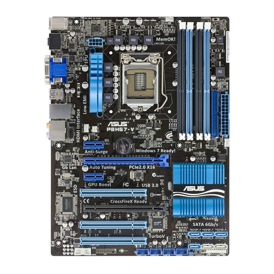
Page 20: Motherboard Layout
KBMS CPU_FAN PWR_FAN MemOK! O2LED2 EATX12V USB3_12 1042 SPDIF_O2 USB56 LGA1155 USB34 LAN1_USB12 AUDIO Lithium Cell CMOS Power CHA_FAN1 AAFP PCIEX1_1 P8H67 32Mb BIOS 8111E PCIEX16_1 PCIEX1_2 1083 Intel ® Super PCI1 SATA3G_3 SATA3G_1 PCIEX16_2 SATA3G_4 SATA3G_2 PCI2 SB_PWR PCI3... -
Page 21: Central Processing Unit (Cpu)
Contact your retailer immediately if the PnP cap is missing, or if you see any damage to the PnP cap/socket contacts/motherboard components. ASUS will shoulder the cost of repair only if the damage is shipment/transit-related. • Keep the cap after installing the motherboard. ASUS will process Return Merchandise Authorization (RMA) requests only if the motherboard comes with the cap on the LGA1155 socket. - Page 22 Lift the load lever in the direction of the arrow until the load plate is completely lifted. Load plate Remove the PnP cap from the CPU socket by lifting the tab only. PnP cap Position the CPU over the socket, ensuring that the gold triangle is on the bottom-left corner of the socket, and CPU notches...
- Page 23 Close the load plate (A), and then push down the load lever (B), ensuring that the front edge of the load plate slides under the retention knob (C). Insert the load lever under the retention tab. ASUS P8H67 1-11...
-
Page 24: Installing The Cpu Heatsink And Fan
1.6.2 Installing the CPU heatsink and fan The Intel LGA1155 processor requires a specially designed heatsink and fan assembly to ® ensure optimum thermal condition and performance. • When you buy a boxed Intel processor, the package includes the CPU fan and ®... -
Page 25: Uninstalling The Cpu Heatsink And Fan
Connect the CPU fan cable to the connector on the motherboard labeled CPU_FAN. CPU_FAN P8H67 P8H67 CPU fan connector Do not forget to connect the CPU fan connector! Hardware monitoring errors can occur if you fail to plug this connector. -
Page 26: System Memory
DDR2 DIMM socket. DDR3 modules are developed for better performance with less power consumption. The figure illustrates the location of the DDR3 DIMM sockets: Channel Sockets Channel A DIMM_A1 and DIMM_A2 P8H67 Channel B DIMM_B1 and DIMM_B2 P8H67 240-pin DDR3 DIMM sockets 1-14 Chapter 1: Product introduction... -
Page 27: Memory Configurations
(4 DIMMs) or overclocking condition. • The Max. 32GB memory capacity can be supported with DIMMs of 8GB (or above). ASUS will update the QVL once the DIMMs are available on market. • Visit the ASUS website at www.asus.com for the latest QVL. - Page 28 P8H67 Motherboard Qualified Vendors List (QVL) DDR3-1333MHz capability DIMM Chip support Vendors Part No. Size Chip No. Timing Voltage Brand A* B* C* A-Data AD31333001GOU A-Data AD30908C8D-151C E0906 - • • • A-Data AD31333G001GOU 3GB(3 x 1GB) SS 8-8-8-24 1.65-1.85V •...
- Page 29 • • • POWER SILICON SP002GBLTU133S02 elixir N2CB1680AN-C6 • • • POWER TAKEMS TMS1GB364D081-107EY 7-7-7-20 1.5V • • TAKEMS TMS2GB364D082-138EW 8-8-8-24 1.5V • • UMAX E41302GP0-73BDB UMAX U2S24D30TP-13 • • WINTEC 3WVS31333-2G-CNR AMPO AM3420803-13H • • • ASUS P8H67 1-17...
- Page 30 DDR3-1066MHz capability DIMM Chip support Vendors Part No. Size SS/DS Chip No. Timing Voltage Brand A* B* C* Crucial CT12864BA1067.8FF Micron 9GF22D9KPT • • • Crucial CT25664BA1067.16FF Micron 9HF22D9KPT • • • 1.35V(low ELPIDA EBJ10UE8EDF0-AE-F ELPIDA J1108EDSE-DJ-F • • • voltage) ELPIDA EBJ11UD8BAFA-AE-E...
-
Page 31: Installing A Dimm
DIMM. Support the DIMM lightly with your fingers when pressing the retaining clips. The DIMM might get damaged when it flips out with extra force. DIMM notch Remove the DIMM from the socket. ASUS P8H67 1-19... -
Page 32: Expansion Slots
Expansion slots In the future, you may need to install expansion cards. The following sub-sections describe the slots and the expansion cards that they support. Unplug the power cord before adding or removing expansion cards. Failure to do so may cause you physical injury and damage motherboard components. - Page 33 • We recommend that you provide sufficient power when running CrossFireX™ mode. See page 1-29 for details. • Connect a chassis fan to the motherboard connector labeled CHA_FAN1 or CHA_FAN2 when using multiple graphics cards for better thermal environment. ASUS P8H67 1-21...
-
Page 34: Jumpers
Normal Clear RTC (Default) P8H67 Clear RTC RAM To erase the RTC RAM: 1. Turn OFF the computer and unplug the power cord. 2. Move the jumper cap from pins 1-2 (default) to pins 2-3. Keep the cap on pins 2-3 for about 5-10 seconds, then move the cap back to pins 1-2. -
Page 35: Connectors
Side Speaker Out port (gray). This port connects the side speaker in an 8-channel audio configuration. Refer to the audio configuration table on the next page for the function of the audio ports in the 2, 4, 6, or 8-channel configuration. ASUS P8H67 1-23... - Page 36 Audio 2, 4, 6, and 8-channel configuration Port Headset 2-channel 4-channel 6-channel 8-channel Light Blue Line In Line in Line in Line in Lime Line Out Front Speaker Out Front Speaker Out Front Speaker Out Pink Mic In Mic In Mic in Mic in Orange...
-
Page 37: Internal Connectors
• Use the 80-conductor IDE cable for Ultra DMA 133/100 IDE devices. If any device jumper is set as “Cable-Select”, ensure that all other device jumpers have the same setting. P8H67 PRI_EIDE PIN1 NOTE:Orient the red markings on the IDE ribbon cable to PIN 1. P8H67 IDE connector ASUS P8H67 1-25... - Page 38 RSATA_TXN4 RSATA_RXP2 RSATA_TXP4 RSATA_RXN2 P8H67 Intel SATA 3.0Gb/s connectors ® • These connectors are set to [AHCI Mode] by default. If you intend to create a Serial ATA RAID set using these connectors, set the SATA Mode item in the BIOS to [RAID Mode].
- Page 39 The connector is for a serial (COM) port. Connect the serial port module cable to the connector, then install the module to a slot opening at the back of the system chassis. The serial port bracket (COM1) is purchased separately. COM1 PIN 1 P8H67 P8H67 Serial port (COM1) connector ASUS P8H67 1-27...
- Page 40 P8H67 fan connectors • The CPU_FAN connector supports a CPU fan of maximum 2A (24 W) fan power. • Only the CPU_FAN, CHA_FAN1 and CHA_FAN2 connectors support the ASUS Fan Xpert feature. • If you install two VGA cards, we recommend that you plug the rear chassis fan cable to the motherboard connector labeled CHA_FAN1 or CAH_FAN 2 for better thermal environment.
- Page 41 The system may become unstable or may not boot up if the power is inadequate. • If you are uncertain about the minimum power supply requirement for your system, refer to the Recommended Power Supply Wattage Calculator at http://support.asus. com/PowerSupplyCalculator/PSCalculator.aspx?SLanguage=en-us for details. ASUS P8H67...
-
Page 42: Usb 2.0 Connectors
P8H67 Front panel audio connector If you want to connect a high-definition front panel audio module to this connector, ensure that the Front Panel Type item in the BIOS is set to [HD Audio]. If you want to connect an AC97 front panel audio module to this connector, set the item to [AC97]. -
Page 43: System Panel Connector
IDE_LED PWRSW RESET * Requires an ATX power supply P8H67 System panel connector • System power LED (2-pin PLED) This 2-pin connector is for the system power LED. Connect the chassis power LED cable to this connector. The system power LED lights up when you turn on the system power, and blinks when the system is in sleep mode. -
Page 44: Onboard Switches
This is ideal for overclockers and gamers who continually change settings to enhance system performance. Turbo Key II switch This switch allows you to enable or disable the Turbo Key II function. Turbo Key II P8H67 P8H67 Turbo Key II switch 1-32 Chapter 1: Product introduction... - Page 45 If the installed DIMMs still fail to boot after the whole tuning process, the DRAM_LED lights continuously. Replace the DIMMs with ones recommended in the Memory QVL (Qualified Vendors Lists) in this user manual or on the ASUS website at www.asus.com.
-
Page 46: Onboard Leds
P8H67 Standby Power Powered Off P8H67 Onboard LED DRAM LED DRAM LED checks the DRAM in sequence during motherboard booting process. If an error is found , the LED next to the error device will continue lighting until the problem is solved. -
Page 47: Software Support
The contents of the Support DVD are subject to change at any time without notice. Visit the ASUS website at www.asus.com for updates. To run the Support DVD Place the Support DVD to the optical drive. - Page 48 1-36 Chapter 1: Product introduction...
-
Page 49: Chapter 2: Bios Information
BIOS in the future. Copy the original motherboard BIOS using the ASUS Update utility. 2.1.1 ASUS Update utility The ASUS Update is a utility that allows you to manage, save, and update the motherboard BIOS in Windows environment. ®... -
Page 50: Asus Ez Flash 2
Follow the onscreen instructions to complete the updating process. 2.1.2 ASUS EZ Flash 2 The ASUS EZ Flash 2 feature allows you to update the BIOS without using an OS-based utility. Before you start using this utility, download the latest BIOS file from the ASUS website at www.asus.com. -
Page 51: Asus Crashfree Bios 3 Utility
2.1.3 ASUS CrashFree BIOS 3 utility The ASUS CrashFree BIOS 3 is an auto recovery tool that allows you to restore the BIOS file when it fails or gets corrupted during the updating process. You can restore a corrupted BIOS file using the motherboard support DVD or a USB flash drive that contains the updated BIOS file. -
Page 52: Asus Bios Updater
2.1.4 ASUS BIOS Updater The ASUS BIOS Updater allows you to update BIOS in DOS environment. This utility also allows you to copy the current BIOS file that you can use as a backup when the BIOS fails or gets corrupted during the updating process. - Page 53 The BIOS Updater backup screen appears indicating the BIOS backup process. When BIOS backup is done, press any key to return to the DOS prompt. ASUSTek BIOS Updater for DOS V1.07 Current ROM Update ROM BOARD: P8H67 BOARD: Unknown VER: 0217 VER:...
-
Page 54: Updating The Bios File
• Ensure to load the BIOS default settings to ensure system compatibility and stability. Select the Load Optimized Defaults item under the Exit menu. Refer to section 2.9 Exit menu for details. • Ensure to connect all SATA hard disk drives after updating the BIOS file if you have disconnected them. ASUS P8H67... -
Page 55: Bios Setup Program
BIOS setup program Use the BIOS Setup program to update the BIOS or configure its parameters. The BIOS screens include navigation keys and brief online help to guide you in using the BIOS Setup program. Entering BIOS Setup at startup To enter BIOS Setup at startup: •... -
Page 56: Bios Menu Screen
Power Saving mode Displays the system properties of the Normal mode ASUS Optimal mode selected mode on the right hand side Selects the boot device priority • The boot device options vary depending on the devices you installed to the system. -
Page 57: Advanced Mode
The Advanced Mode provides advanced options for experienced end-users to configure the BIOS settings. The figure below shows an example of the Advanced Mode. Refer to the following sections for the detailed configurations. To access the EZ Mode, click Exit, then select ASUS EZ Mode. Back button Menu bar... -
Page 58: Menu Items
You cannot select an item that is not user-configurable. A configurable field is highlighted when selected. To change the value of a field, select it and press <Enter> or click on it to display a list of options. 2-10 ASUS P8H67... -
Page 59: Main Menu
Main menu The Main menu screen appears when you enter the Advanced Mode of the BIOS Setup program. The Main menu provides you an overview of the basic system information, and allows you to set the system date, time, language, and security settings. EFI BIOS Utility - Advanced Mode Exit Main... -
Page 60: Administrator Password
To clear the user password, follow the same steps as in changing a user password, but press <Enter> when prompted to create/confirm the password. After you clear the password, the User Password item on top of the screen shows Not Installed. 2-12 ASUS P8H67... -
Page 61: Ai Tweaker Menu
Ai Tweaker menu The Ai Tweaker menu items allow you to configure overclocking-related items. Be cautious when changing the settings of the Ai Tweaker menu items. Incorrect field values can cause the system to malfunction. The configuration options for this section vary depending on the CPU and DIMM model you installed on the motherboard. -
Page 62: Memory Frequency
This item appears only when you set the EIST item to [Enabled]. [Enabled] Allows processor cores to run faster than marked frequency in specific conditions. [Disabled] Disables this function. The following three items appear only when you set both the EIST and Turbo Mode items to [Enabled]. 2-14 ASUS P8H67... -
Page 63: Cpu Offset Mode Sign
Long duration power limit [Auto] Use <+>/<-> to adjust the value. Long duration maintained [Auto] Use <+>/<-> to adjust the value. Short duration power limit [Auto] Use <+>/<-> to adjust the value. Power Limit Control [Disabled] Allows you to enable or disable the power limit control function. Configuration options: [Disabled] [Enabled] The following two items appear only when you set the Power Limit Control item to [Enabled]. -
Page 64: Vccio Voltage
Load-Line Calibration [Auto] Allows you to enable or disable the Load-Line calibration function. Configuration options: [Auto] [Disabled] [Enabled] 2.4.13 CPU Spread Spectrum [Auto] [Auto] Automatic configuration. [Disabled] Enhances the BCLK overclocking ability. [Enabled] Sets to [Enabled] for EMI control. 2-16 ASUS P8H67... -
Page 65: Advanced Menu
Advanced menu The Advanced menu items allow you to change the settings for the CPU and other system devices. Be cautious when changing the settings of the Advanced menu items. Incorrect field values can cause the system to malfunction. EFI BIOS Utility - Advanced Mode Exit Ai Tweaker Main... - Page 66 Allows processor cores to run faster than marked frequency in specific condition. [Disabled] Disables this function. CPU C1E [Enabled] [Enabled] Enables the C1E support function. This item should be enabled in order to enable the Enhanced Halt State. [Disabled] Disables this function. 2-18 ASUS P8H67...
-
Page 67: System Agent Configuration
CPU C3 Report [Disabled] Allows you to disable or enable the CPU C3 report to OS. Configuration options: [Disabled] [ACPI C-2] [ACPI C-3] CPU C6 Report [Enabled] Allows you to disable or enable the CPU C6 report to OS. Configuration options: [Enabled] [Disabled] 2.5.2 System Agent Configuration The System Agent Configuration menu allows you to change the System Agent settings. -
Page 68: Usb Configuration
Legacy US3.0 Support [Enabled] [Enabled] Enables the support for USB 3.0 devices on legacy operating systems (OS). [Disabled] Disables the function. EHCI Hand-off [Disabled] [Enabled] Enables the support for operating systems without an EHCI hand-off feature. [Disabled] Disables the function. 2-20 ASUS P8H67... -
Page 69: Onboard Devices Configuration
2.5.6 Onboard Devices Configuration HD Audio Controller [Enabled] [Enabled] Enables the High Definition Audio Controller. [Disabled] Disables the controller. The following two items appear only when you set the HD Audio Controller item to [Enabled]. Front Panel Type [HD] Allows you to set the front panel audio connector (AAFP) mode to legacy AC’97 or high- definition audio depending on the audio standard that the front panel audio module supports. -
Page 70: Serial Port Configuration
Allows you to enable or disable the serial port (COM). Configuration options: [Enabled] [Disabled] Change Settings [IO=3F8h; IRQ=4] Allows you to select the Serial Port base address. Configuration options: [IO=3F8h; IRQ=4] [IO=2F8h; IRQ=3] [IO=3E8h; IRQ=4] [IO=2E8h; IRQ=3] 2-22 ASUS P8H67... -
Page 71: Apm
2.5.7 Restore AC Power Loss [Power Off] [Power On] The system goes into on state after an AC power loss. [Power Off] The system goes into off state after an AC power loss. [Last State] The system goes into either off or on state, whatever the system state was before the AC power loss. -
Page 72: Monitor Menu
The onboard hardware monitor automatically detects and displays the CPU, chassis, and power fan speeds in rotations per minute (RPM). If the fan is not connected to the motherboard, the field shows N/A. Select Ignore if you do not wish to display the detected speed. 2-24 ASUS P8H67... -
Page 73: Cpu Q-Fan Control
2.6.3 CPU Q-Fan Control [Enabled] [Disabled] Disables the CPU Q-Fan control feature. [Enabled] Enables the CPU Q-Fan control feature. CPU Fan Speed Low Limit [600 RPM] This item appears only when you enable the CPU Q-Fan Control feature and allows you to disable or set the CPU fan warning speed. -
Page 74: Cpu Voltage, 3.3V Voltage, 5V Voltage, 12V Voltage
The onboard hardware monitor automatically detects the voltage output through the onboard voltage regulators. Select Ignore if you do not want to detect this item. 2.6.6 Anti Surge Support [Enabled] This item allows you to enable or disable the Anti Surge function. Configuration options: [Disabled] [Enabled] 2-26 ASUS P8H67... -
Page 75: Boot Menu
[Disabled] Disables the full screen logo display feature. Set this item to [Enabled] to use the ASUS MyLogo 2™ feature. Post Report [5 sec] This item appears only when the Full Screen Logo item is set to [Disabled] and allows you to set the waiting time for the system to display the post report. -
Page 76: Option Rom Messages
• To select the boot device during system startup, press <F8> when ASUS Logo appears. • To access Windows OS in Safe Mode, do any of the following: - Press <F5>... -
Page 77: Tools Menu
> ASUS O.C. Profile 2.8.1 ASUS EZ Flash 2 Allows you to run ASUS EZ Flash 2. When you press <Enter>, a confirmation message appears. Use the left/right arrow key to select between [Yes] or [No], then press <Enter> to confirm your choice. -
Page 78: Exit Menu
Load Optimized Defaults Save Changes & Reset Discard Changes & Exit ASUS EZ Mode Launch EFI Shell from filesystem device Load Optimized Defaults This option allows you to load the default values for each of the parameters on the Setup menus. -
Page 79: Asus Contact Information
+1-510-739-3777 +1-510-608-4555 Web site usa.asus.com Technical Support Telephone +1-812-282-2787 Support fax +1-812-284-0883 Online support support.asus.com ASUS COMPUTER GmbH (Germany and Austria) Address Harkort Str. 21-23, D-40880 Ratingen, Germany +49-2102-959911 Web site www.asus.de Online contact www.asus.de/sales Technical Support Telephone (Component) +49-1805-010923*...
Need help?
Do you have a question about the P8H67 and is the answer not in the manual?
Questions and answers